

Fastening device for a fuel injection valve
a technology of fastening device and fuel injection valve, which is applied in the direction of fuel injection apparatus, machine/engine, feed system, etc., can solve the problems of increasing the space required for mounting, changing the valve needle, and the stressing effect of the clamping claw on the fuel injector
- Summary
- Abstract
- Description
- Claims
- Application Information
AI Technical Summary
Benefits of technology
Problems solved by technology
Method used
Image

Examples
Embodiment Construction
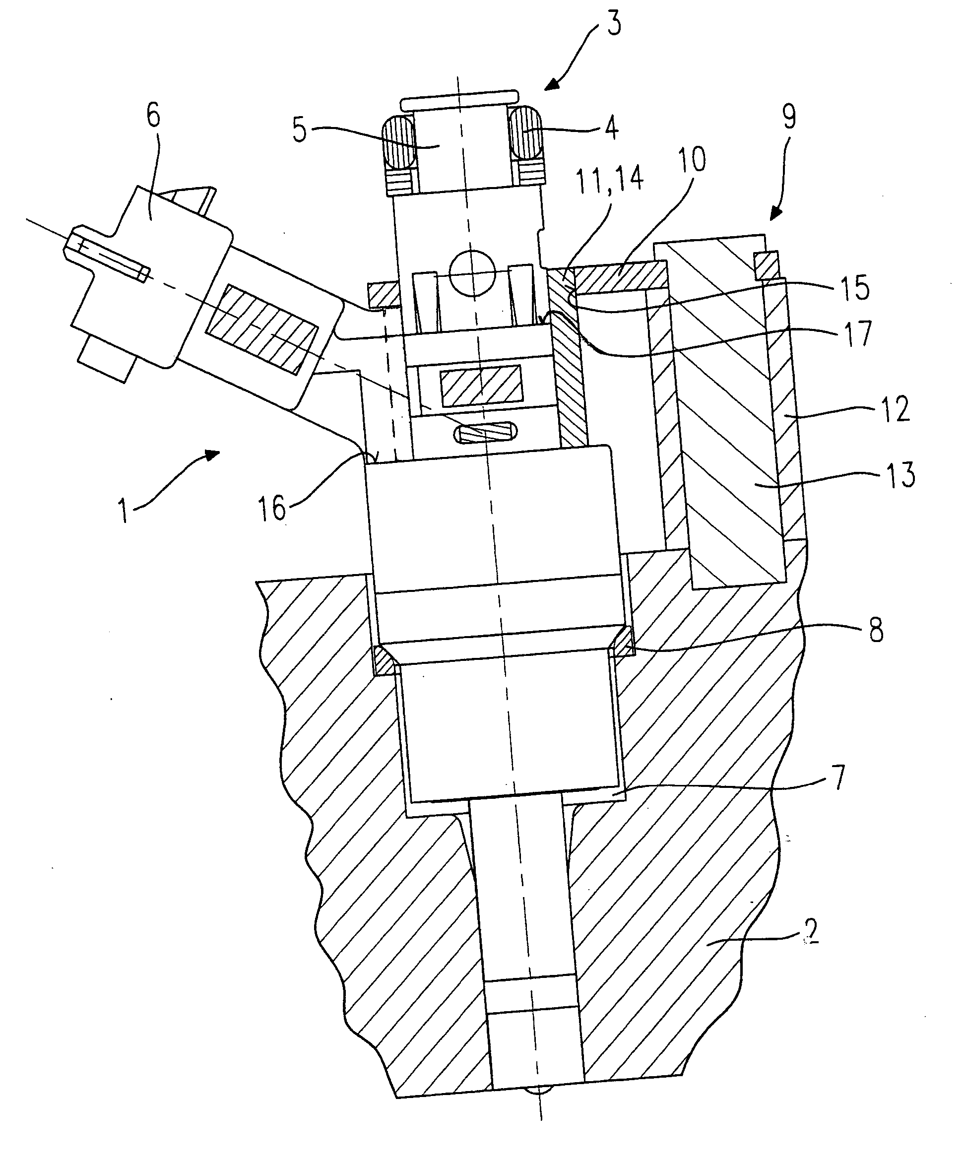
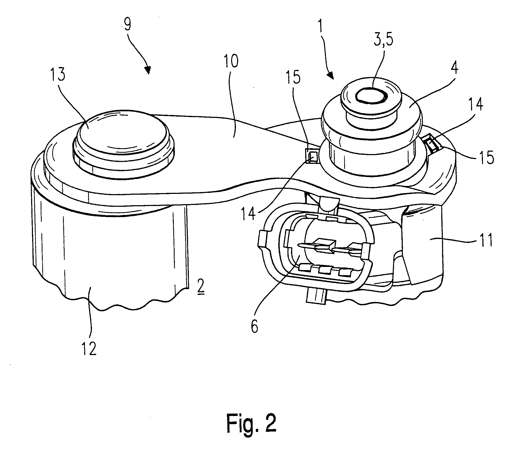
[0012] FIG. 1 shows a schematic and simplified view of an exemplary embodiment of a mounting device for a fuel injector on a cylinder head of an internal combustion engine, designed according to the present invention, where, for the sake of clarity, mounting device 9 and fuel injector 1, viewed in the perimeter direction, are not illustrated in their exact relative positions.
[0013] Fuel injector 1 is designed here in the form of a direct injecting fuel injector 1, which is mounted in a cylinder head 2 for direct injection of fuel into a combustion chamber of a mixture-compressing, spark-ignited engine (not shown). At its upstream end 3, fuel injector 1 has a plug-in connection to a fuel distribution line (not shown) which is sealed by a gasket 4 situated between the fuel distribution line and a feed line connection 5 of fuel injector 1. Fuel injector 1 has an electrical terminal 6 for the electrical contact for actuation of fuel injector 1.
[0014] Fuel injector 1 has an intermediate ...
PUM
 Abstract
Description
Claims
Application Information