Locating system and method for determining positions of objects

Inactive Publication Date: 2004-02-05
NIPPON TELEGRAPH & TELEPHONE CORP
View PDF7 Cites 37 Cited by
  • Summary
  • Abstract
  • Description
  • Claims
  • Application Information

AI Technical Summary

Benefits of technology

0037] With the second correcting formula, the propagation rate of a signal carried by electromagnetic waves or ultrasonic waves is determined based on the actually measured values (e.sub.ij and t.sub.ij), using an approximate function. Consequently, it is not necessary to additionally measure the temperature and the humidity of the air for the correction. In addition, since the relation between the propagation time and the distance is corrected based on the actually measured values, the estimation accuracy is improved even if high-speed operation can not be carried out due to aiming to achieve low power consumption.
0038] The positioning system may include a single fixed-position receiving station (i.e., a first receiving station) and a single moving receiving station (i.e., a second receiving station) in order to reduce the number of the fixed-position receiving stations that function as base stations. This arrangement also allows the system to correctly estimate the position of a transmitting station that has moved away from the communication area of the fixed-position receiving station. In this case, the positioning computer determines at least one of the first and secon

Problems solved by technology

However, the communication range is limited to several tens of centimeters, and therefore it is unsuitable for a long-range tag system.
This causes a problem that precise position information can not be obtained when such position information is actually needed.
Still another problem is that there is no information about the environment of the transmitting station.
Thus, the conventional "passive tag system" is unsuitable for a long-range radio tag system because its communication range is as short as several ten centimeters.
For this reason, it is difficult for this system to obtain accurate position information when it is actually required.
In addition, at least three base stations have to be fixed to estimate the posi

Method used


Image

  • Locating system and method for determining positions of objects
  • Locating system and method for determining positions of objects
  • Locating system and method for determining positions of objects

Examples


first embodiment

[0092] [First Embodiment]

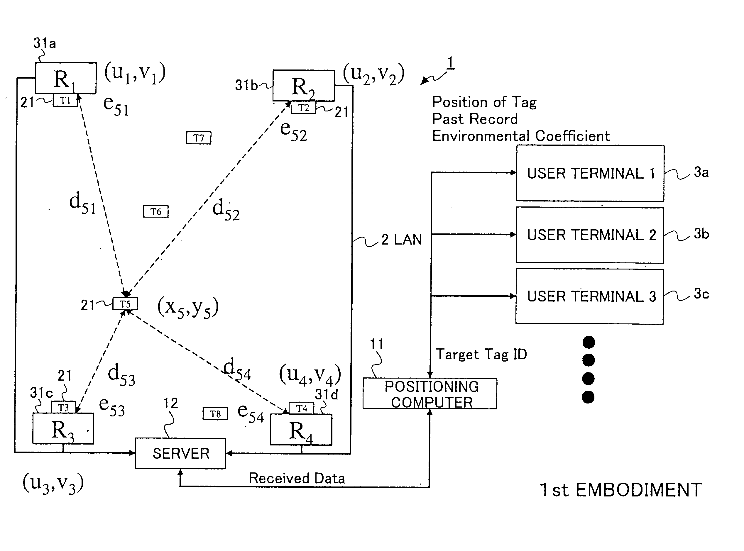
[0093] FIG. 5 schematically illustrates an example of the locating system 1 according to the first embodiment of the invention, and FIG. 6 illustrates the transmitting station 21 and the receiving station 31 used in the locating system 1. The locating system 1 includes transmitting stations 21 (T1-T8), receiving stations 31 (R1-R4), a server 12 connected to the receiving stations 31 and functioning as a data management unit, and a positioning computer 11 connected to the server 12. The locating system 1 also includes user terminals 3a-3c connected to the positioning computer 11. These components are connected to one another via LAN 2.

[0094] In the example shown in FIG. 5, the receiving stations 31 (R1-R4) are fixed, and their positions are known. The transmitting stations T1-T4 are attached to the receiving stations R1-R4, respectively, and therefore, the positions of the transmitting stations T1-T4 can be regarded the same as those of the receiving stations...

second embodiment

[0135] [Second Embodiment]

[0136] FIG. 10 illustrates a schematic diagram of the locating system according to the second embodiment of the invention, and FIG. 11 illustrates the transmitting station 21 and the receiving station 31 used in the second embodiment. In the second embodiment, the receiving station periodically transmits an activation signal to the transmitting station. The transmitting station transmits an ID signal, which is different from the spontaneously generated ID signal, upon receiving the activation signal. Accordingly, the transmitting station generates three different kinds of ID signals, that is, (1) a periodic signal (i.e., the first ID signal) spontaneously generated by, for example, a built-in oscillator, (2) a signal (i.e., the second ID signal) generated in response to the activation signal, and (3) a signal (i.e., the third ID signal) generated when detecting a change due to external factors.

[0137] In the example shown in FIG. 10, both the activation sign...

third embodiment

[0185] [Third Embodiment]

[0186] FIG. 22 is a schematic diagram of the locating system according to the third embodiment of the invention, and FIG. 23 illustrates the transmitting station 21 and the receiving station 31 used in the third embodiment. In the third embodiment, the receiving station 31 has a means for measuring a transmission time required to acquire a type-a ID signal in response to the activation signal. Accordingly, as illustrated in FIG. 22, the receiving station R1 measures a transmission time t51 required to acquire the ID signal from transmitting station T5, in addition to the intensity e51. The other fixed-position receiving stations R2-R4 also measure the intensity and the ID signal transmission time.

[0187] In the third embodiment, a second correcting formula defining a relation between signal propagation time through the air and distance is used. By using the second correcting formula, the position of a transmitting station can be estimated more accurately. The...


PUM


Abstract

A locating system for determining a position of an object comprises a transmitting station that transmits a first ID signal containing a first identifier of this transmitting station; a receiving station that receives the first ID signal, measures the intensity of the first ID signal, and extracts the first identifier; a data management unit that stores and manages the intensity in association with the first identifier, the intensity and the identifier being supplied from the receiving station; and a positioning computer that estimates the position of the transmitting station using a first correcting formula defining a relation between the intensity and the distance, based on the data stored in the data management unit.

Description

[0001] 1. Field of Invention[0002] The present invention generally relates to a locating system for determining the location of a transmitting station attached to an item or a person, and more particularly to a locating system for efficiently determining the positions of a number of transmitting stations indoors, such as in stores, warehouses, and offices, with a high precision without being subjected to much influence from environmental factors.[0003] 2. Description of the Related Art[0004] Wireless tags (or transmitting stations) are used in various fields. For example, a tag system illustrated in FIG. 1 is actually working at many stores. The system shown in FIG. 1 comprises a gate 121 and wireless tags 123 attached to items or merchandise. If items 122a and 122b having tags 123a and 123b, respectively, pass through the gate 121 without paying at a cashier, the system generates alarms. This system is a so-called passive tag system using gates, in which passive tags are used as tr...

Claims


Application Information

Patent Timeline
IPC IPC(8): F41G3/26G01S11/06G01S11/12G01S11/14
CPCF41G3/2633G01S11/14G01S11/12G01S11/06
Inventor HAYASHI, HITOSHISHIMIZU, MASASHISUDA, HIROHITOSHIBUYA, AKINORI
Owner NIPPON TELEGRAPH & TELEPHONE CORP
Why Eureka
Try Eureka