Electromagnetic actuator and integrated actuator and fluid flow control valve

a technology of integrated actuators and actuators, applied in the direction of electromagnets, dynamo-electric machines, combustion processes, etc., can solve the problems of significant wear, no attempt to store energy, shorten the life of devices, etc., and achieve low driving energy, fast response, and long life span

Inactive Publication Date: 2004-02-12
CAMCOM
View PDF1 Cites 81 Cited by
  • Summary
  • Abstract
  • Description
  • Claims
  • Application Information

AI Technical Summary

Benefits of technology

0143] Such an arrangement is extremely beneficial securing not only fast res

Problems solved by technology

However no attempt is made to store energy during armature movement, subsequently to accelerate the armature in transit between its two positions.
In addition the arma

Method used


Image

  • Electromagnetic actuator and integrated actuator and fluid flow control valve
  • Electromagnetic actuator and integrated actuator and fluid flow control valve
  • Electromagnetic actuator and integrated actuator and fluid flow control valve

Examples


Embodiment Construction

[0144] The invention will now be described by way of example with reference to the accompanying drawings, in which:--

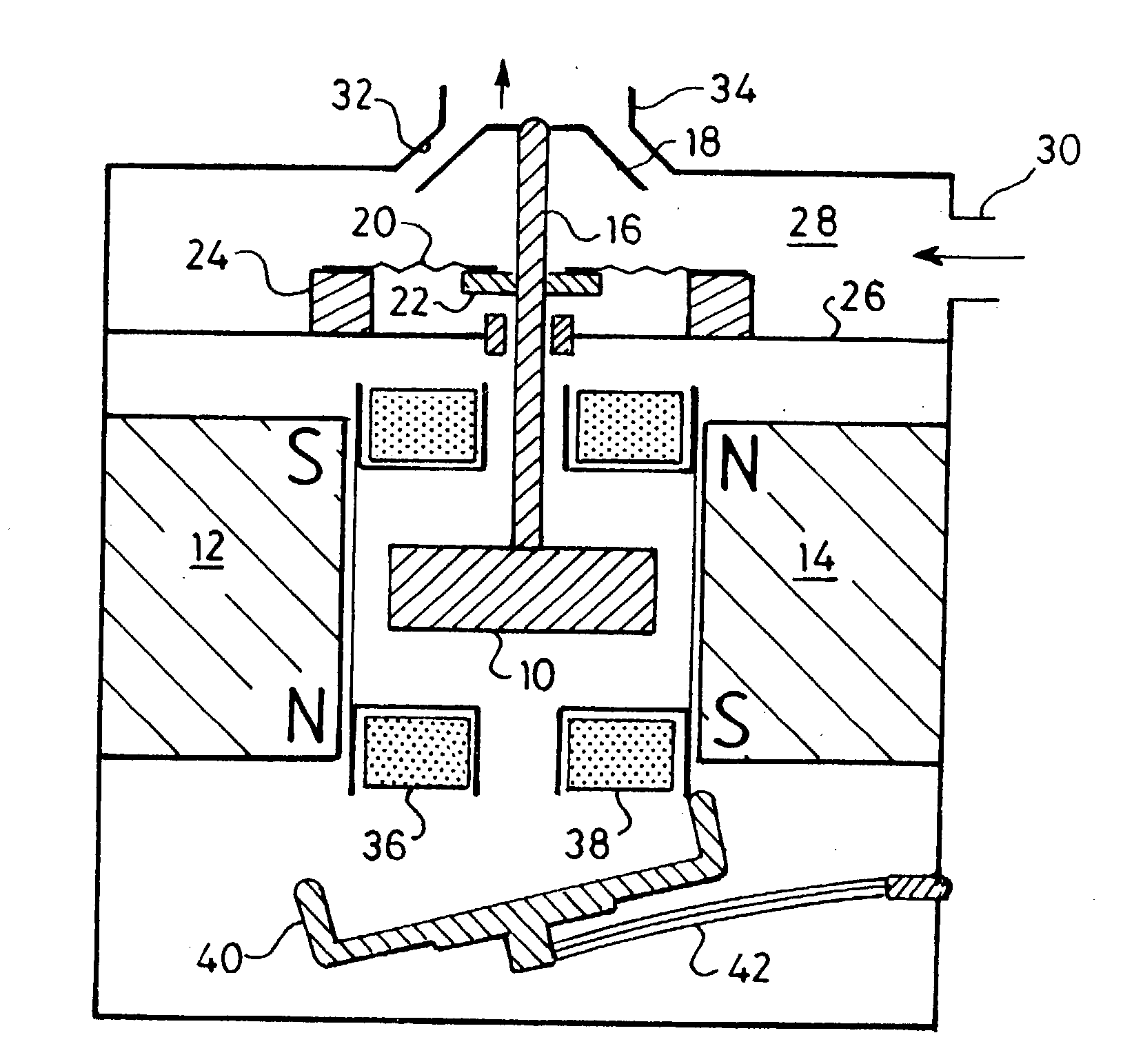
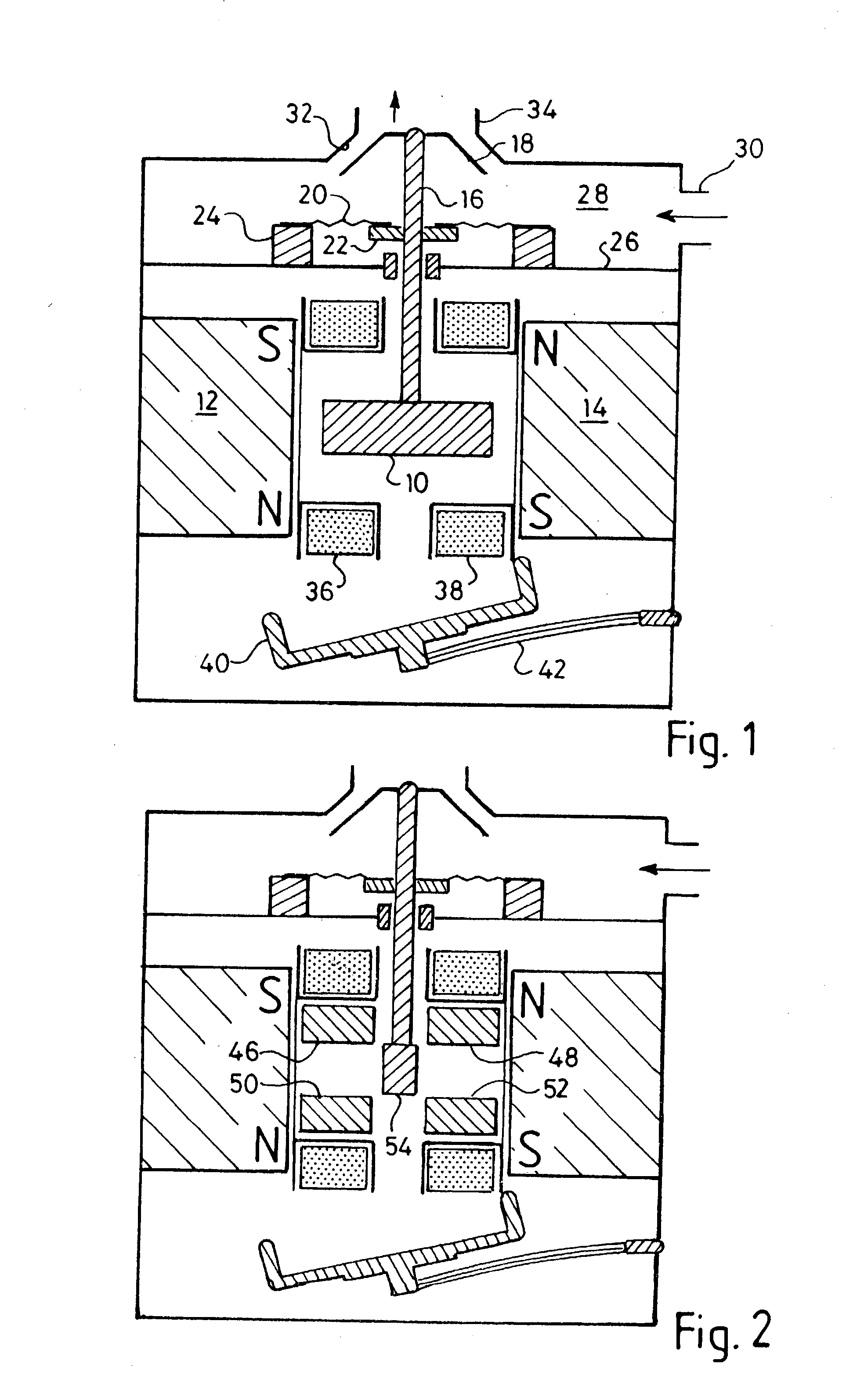
[0145] FIG. 1 is a cross-section through a magnetic drive which can be bistable or monostable depending on whether or not a flux short-circuiting element is in position;

[0146] FIG. 2 illustrates a similar arrangement to that of FIG. 1, but in which the armature is split into a number of parts most of which are stationary so as to reduce the mass of the moving part of the armature;

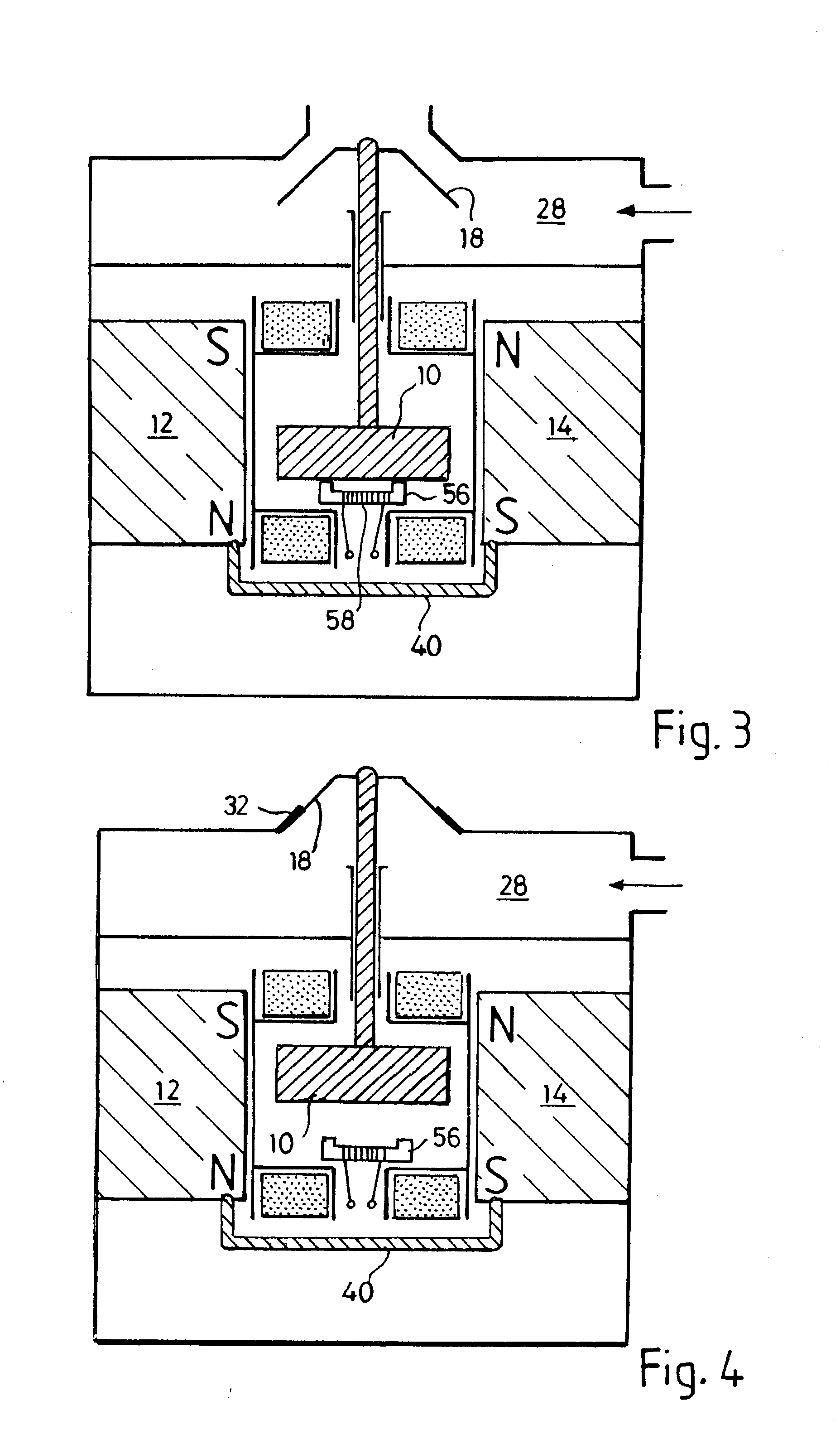
[0147] FIG. 3 is a further cross-section through a device similar to that of FIG. 1 in which electromagnetic means is provided for holding the movable armature in a position from it would normally move as a result of the reduction in magnetic flux by movement of the flux short-circuiting device;

[0148] FIG. 4 illustrates the arrangement of FIG. 3 in which the electromagnetic holding device has been disabled allowing the armature to shift to the other end of the drive;

[0149] FIG. 5 shows the ma...


PUM


Abstract

A magnetic device is formed from a permanent magnet generating magnetic flux, an armature which can occupy two positions between four poles and an electromagnet winding to which current can be supplied to produce a magnetic flux in one direction or the other, the flux from the winding causing the armature to move into one position and continue to remain in that position after the current flow ceases. The device can be incorporated into a fluid valve to act as a drive for opening and closing the valve. It may also serve as the drive for opening and closing electrical contacts. Monostable operation can be achieved by locating a magnetic flux shunt at one end of the armature travel. A holding solenoid may be incorporated. A pivoting armature in a fluid tight chamber comprises a fluid flow controlling device. It can adopt either of two home positions in contact with two magnetic poles and is retained by magnetic flux from a permanent magnet. Fluid can flow into and out of the chamber via a first passage. A second passage extends through one of the poles to an opening in the pole face which is covered by the armature when the latter occupies one home position but is uncovered when the armature occupies its other home position. A third fluid passage extends through and leads to a second opening in another pole, which is covered when the armature occupies its said other home position. Passages in the poles house energy storing springs each of which is compressed as the armature approaches the pole. A push rod can extend through a passage in one of the poles for conveying armature movement externally of the device.

Description

[0001] This invention concerns electromagnetic actuators and in particular a design of actuator which can be integrated into a fluid flow control valve. Such valves can be used to control gas or liquid flow, and actuators can be made to open and close electrical switch contacts.BACKGROUND TO THE INVENTION[0002] Magnetic attraction and repulsion is commonly employed as a motive force to operate devices such as valve closure members, pistons in cylinders to achieve a pumping action, and contactors and switches for opening and closing electrical circuits.[0003] Such drives may have a bistable or monostable characteristic, and often employ a spring force to provide a restoring force and create a monostable operating characteristic.[0004] Magnetic fields to achieve the operation are usually generated by causing an electric current to flow in a winding surrounding a ferromagnetic core or the like, which if the magnetic field is to collapse when the current flow ceases (as is usually requi...

Claims


Application Information

Patent Timeline
IPC IPC(8): F16K31/06F16K31/08H01F7/08H01F7/122H01F7/14H01F7/16H01H51/22
CPCF16K31/0682F16K31/082H01F7/081H01H51/2209H01F7/14H01F7/1615H01F7/1646H01F7/122Y10T137/1516Y10T137/86445
Inventor WYGNASKI, WLADYSLAW
Owner CAMCOM
Why Eureka
Try Eureka