Pourer with improved locking and cap equipped with same

Inactive Publication Date: 2004-02-12
PECHINEY CAPSULES
View PDF13 Cites 16 Cited by
  • Summary
  • Abstract
  • Description
  • Claims
  • Application Information

AI Technical Summary

Problems solved by technology

Under these conditions, some closure caps may be damaged as a result of the magnitude of this force, particularly by buckling of the skirt or modification of easy opening means.
Therefore, the problem to be solved is to have a pourer which can be attached to the neck by

Method used


Image

  • Pourer with improved locking and cap equipped with same
  • Pourer with improved locking and cap equipped with same
  • Pourer with improved locking and cap equipped with same

Examples


example embodiments

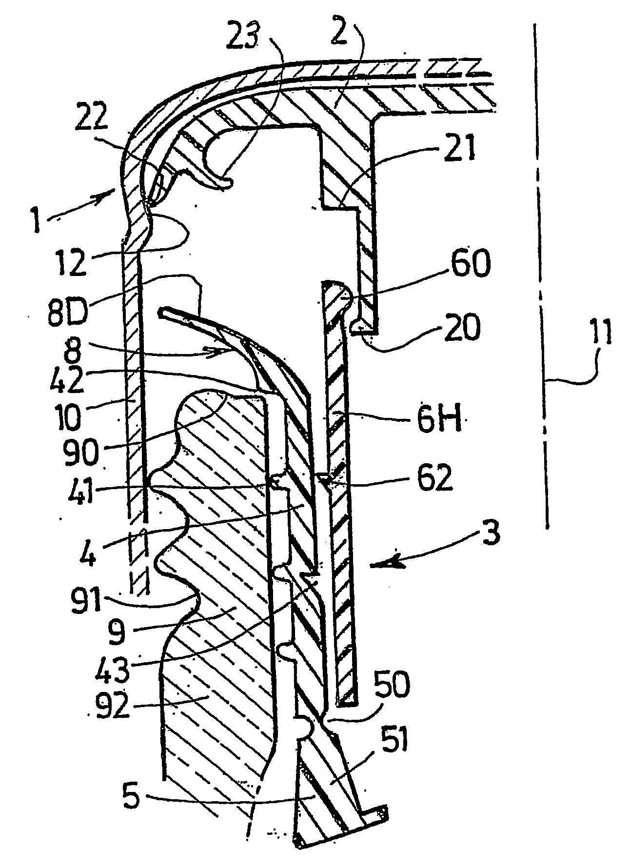
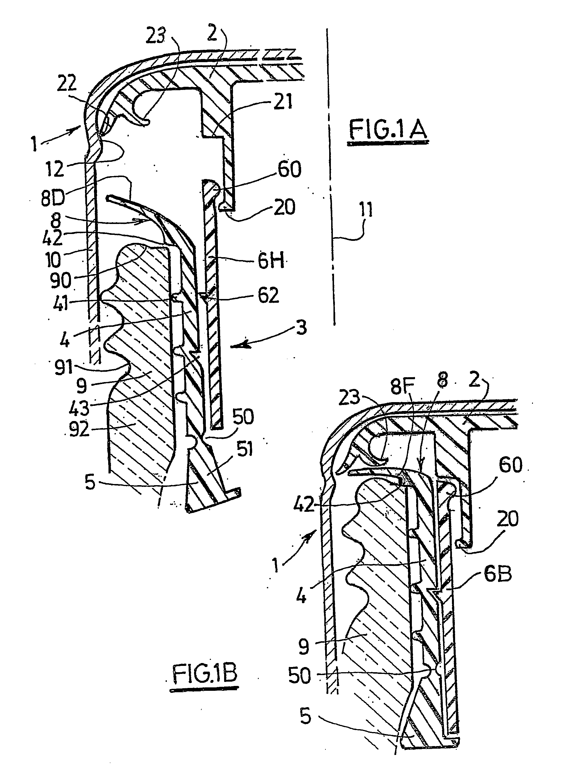
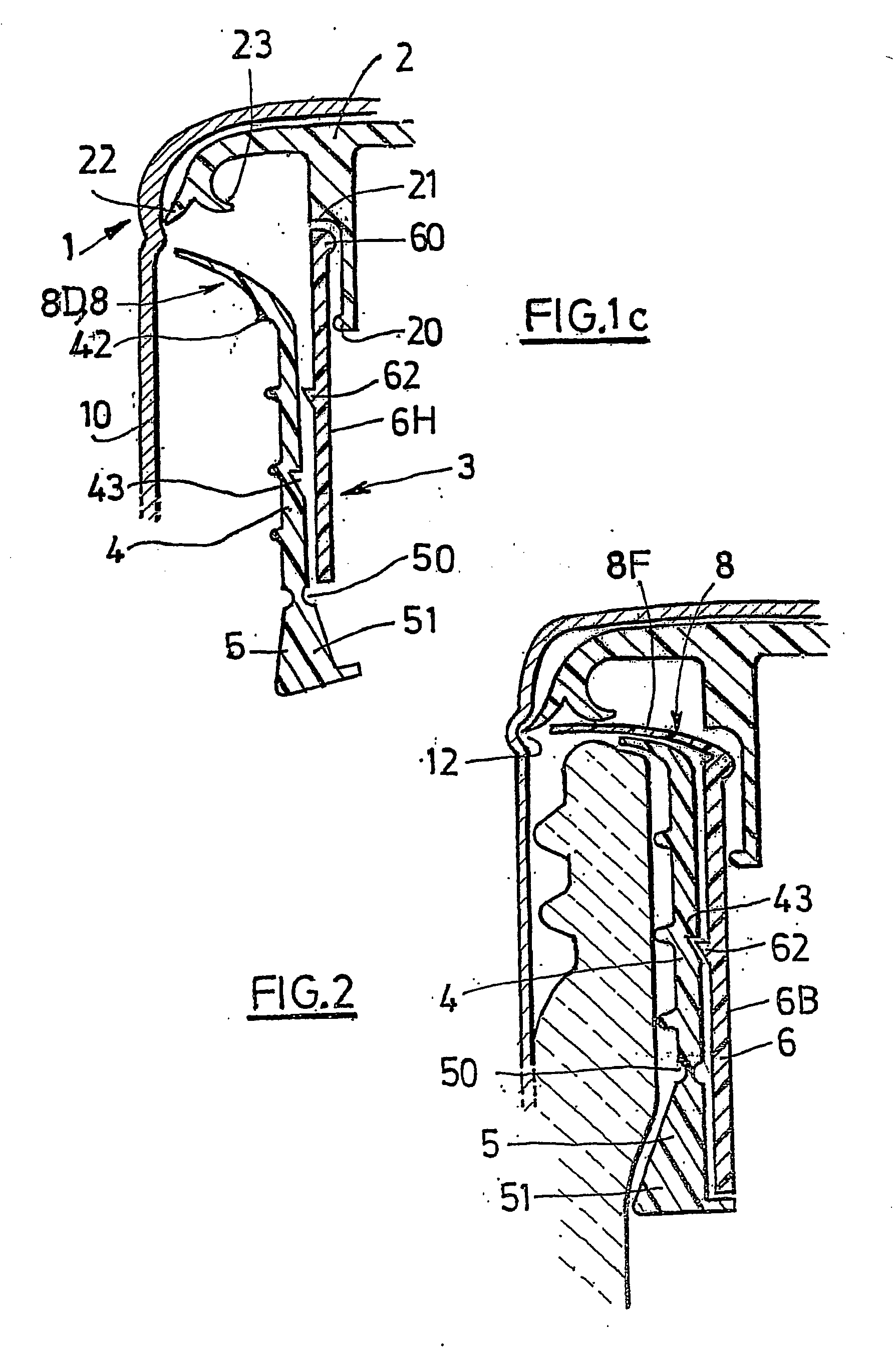
[0073] The figures show example embodiments of caps (1) fitted with inserts (2) and with pourers (3) according to the invention.

[0074] In these examples, all caps and pourers were made for closing necks with an outside diameter of 31.5 mm--see FIG. 7A.

[0075] A conventional shell, typically made of aluminium, was used for the metallic part (10) of the cap.

[0076] As can be seen in the Figures, all the inserts (2) include the following elements:

[0077] 1--a peripheral lip (22) to rigidly fix the insert with the metallic part (10) by means of an annular groove (12), otherwise the insert would have to be glued to the head of the metallic part (10),

[0078] 2--a sealing lip (23) facing inwards and which is preferably compressed in contact with the edge (90) as illustrated in FIGS. 10B to 11B, but possibly in contact with the flexible lip (8F) as illustrated in the other figures.

[0079] 3--a temporary means of assembling the insert (2) to the pourer (3) that solidarises the cap and the pourer ...


PUM


Abstract

The invention concerns a pourer (3) associated with a closure cap (1) and designed to be fixed inside a container neck (9), comprising a peripheral skirt (4), a pouring element (8), and means for temporarily assembling said pourer and said closure cap. The invention is characterised in that: a) said peripheral skirt (4) comprises a lower part (5) capable of being radially spaced apart for the pourer to be fixed to the neck; b) the pourer (3) comprises a rigid component (6) axially mobile downwards, inside the peripheral skirt (4); c) the pourer (3) comprises means for causing the lower part (5) and the rigid component (6) to co-operate so as to transform the axial movement of the rigid component (6) into a radial movement of the lower part (1).

Description

[0001] The invention relates to the field of containers, usually bottles, the orifice of which is provided with a pourer, typically for packaging liquors, aperitifs, alcohol.STATE OF THE ART[0002] Many different types of pourers associated with closure caps are already known, distinguished particularly by their method of attachment to the container neck and by the pouring element itself.[0003] The pouring element itself may either have a fixed configuration as shown in FIGS. 1 and 2 or a variable configuration, and particularly an axially mobile configuration as described in patents FR 2.057.345, GB 922,188, U.S. Pat. No. 3,217,935 and U.S. Pat. No. 4,569,464.[0004] Concerning the method of attachment to the container neck, the pourer may be force fitted into the neck, being usually provided with circular sealing ribs as shown in FIG. 2 and described in patents FR 2.057.345, GB 922,188 and U.S. Pat. No. 3,217,935.[0005] Problem that Arises[0006] These pourers are associated with a c...

Claims


Application Information

Patent Timeline
IPC IPC(8): B65D47/06B65D49/04
CPCB65D47/061B65D49/04B65D47/063
Inventor GRANGER, JACQUESBOURREAU, JEAN-MARIE
Owner PECHINEY CAPSULES
Why Eureka
Try Eureka