
Method and apparatus for reducing the visual effects of nonuniformities in display systems

a display system and non-uniformity technology, applied in the field of methods and techniques for reducing the visual impact of non-uniformity of cell gap and drive voltage in liquid crystal display, can solve the problems of inconvenient methods available to solve this problem, inability to use random spacer balls, and inability to meet the needs of the user

Active Publication Date: 2004-02-12
GOOGLE LLC
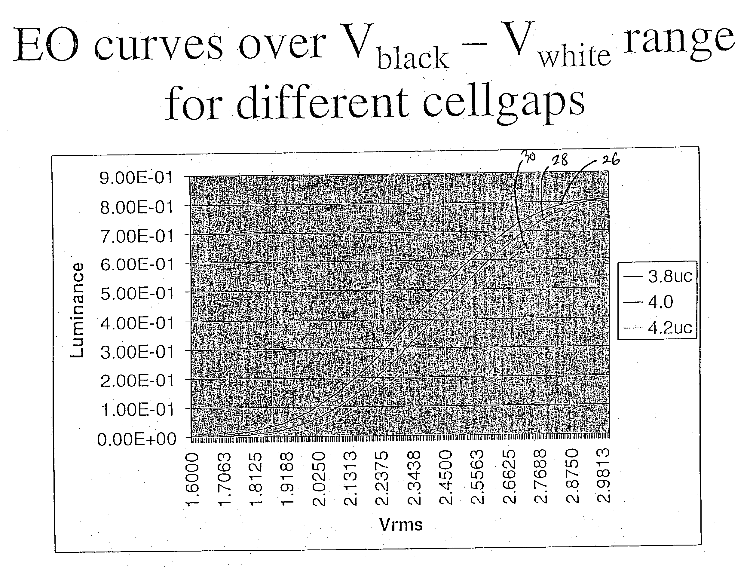
View PDF6 Cites 20 Cited by
  • Summary
  • Abstract
  • Description
  • Claims
  • Application Information

AI Technical Summary

Benefits of technology

[0017] Another object of the present invention is to provide improved methods for adjusting optical output from displays which increase the yield from current display manufacturing processes.
[0018] Yet another object of the present invention is to provide improved controllers and their methods of use, that provide the improved nonuniformity compensation scheme.
[0022] In another embodiment of the present invention, a method is provided for reducing visual impact of cell gap and drive voltage nonuniformities on a liquid crystal display. The method comprises correcting luminous output at a given point on the display by making a weighted interpolation between horizontal correction factors for a cell and vertical correction factors for the same cell and averaging the two correction factors. The method further includes applying an averaged correction factor to adjust voltage to the display.

Problems solved by technology

Additionally there are methods available to solve this problem that are not suitable in the microdisplay environment.
The present problem is the one of nonuniformities in microdisplays used in displays that magnify the images created by the microdisplays.
Spacers are undesirable in certain display applications and have proved problematic in liquid crystal on silicon display.
The use of random spacer balls has been evaluated at great length and found to be unacceptable.
While this problem exists to a small degree in direct view panels, the effects are normally negligible, whereas the effects in the magnified images of projection displays become objectionable and threaten the commercial success of the product.
This is not a complete solution because the three microdisplays are normally aligned using a combination of mechanical alignment and electronic image convergence.
While preferable, this leads back to the fundamental problem of uniformity across the aperture of the display device.
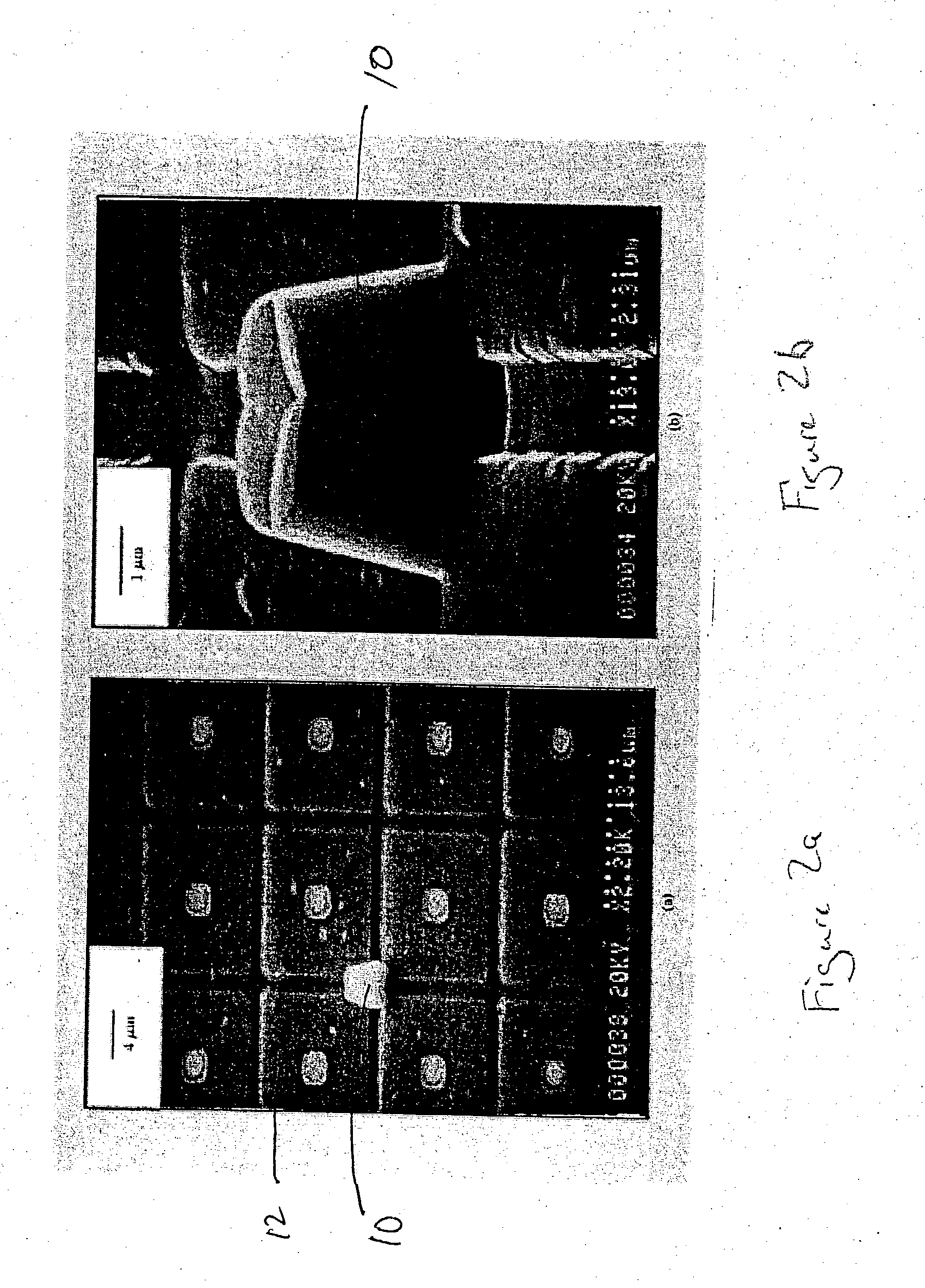
While the resulting surface is much better than the original surface it still is not as flat as a piece of highly polished glass.
In such cases a slight change in rubbing density due to surface topology can create a slight difference to the liquid crystal pretilt which in turn can change the effective birefringence of that part of the cell and thus result in a nonuniformity in the cell.
An additional source of variance is the delivery of nonuniform voltages to the pixel electrodes associated with a image.
Common causes include improper or nonuniform line impedance matching, use of low cost CMOS digital to analog converters without calibration, and lack of uniform and consistent pixel capacitor size in DRAM based microdisplays manufactured in CMOS processes.

Method used


Image

  • Method and apparatus for reducing the visual effects of nonuniformities in display systems
  • Method and apparatus for reducing the visual effects of nonuniformities in display systems
  • Method and apparatus for reducing the visual effects of nonuniformities in display systems

Examples


Embodiment Construction

[0039] It is to be understood that both the foregoing general description and the following detailed description are exemplary and explanatory only and are not restrictive of the invention, as claimed. It should be noted that, as used in the specification and the appended claims, the singular forms "a", "an" and "the" include plural referents unless the context clearly dictates otherwise.

[0040] Thus, for example, reference to "a material" may include mixtures of materials, reference to "an LED" may include multiple LEDs, and the like. References cited herein are hereby incorporated by reference in their entirety, except to the extent that they conflict with teachings explicitly set forth in this specification.

[0041] In this specification and in the claims which follow, reference will be made to a number of terms which shall be defined to have the following meanings:

[0042] "Optional" or "optionally" means that the subsequently described circumstance may or may not occur, so that the ...


PUM


Abstract

A method is provided for compensating for output nonuniformity on a display. The method comprises characterizing the display. The method further includes creating a set of data tables wherein one table provides data for compensation along vertical axes of the display and a second table provided data for compensation along horizontal axes of the display, and wherein components of the tables include a linear offset factor to correct data for nonuniformity and a slope factor which permits gray scale information to be recovered at points near the limits of the gray scale range. The characterizing step may include using a optical detector to obtain optical output information from the display. The slope factor may be calculated to preserve top end gray scale range of the display by adjusting luminous output so that input data level maps to separate output grey levels between a truncated and an untruncated level.

Description

[0001] This application claims the benefit of priority to U.S. Provisional Patent Application Ser. No. 60 / 381,349 (Attorney Docket No. 2002 / 004) filed May 17, 2002. All applications listed above are incorporated herein by reference for all purposes.[0002] 1. Technical Field of the Invention[0003] This invention relates to methods and techniques for reducing the visual impact of cell gap and drive voltage nonuniformities in liquid crystal displays, and more particularly to projection and other magnified displays based on liquid crystal on silicon microdisplays.[0004] 2. Discussion of Related Art[0005] Liquid crystal displays and more particularly liquid crystal on silicon microdisplays are very sensitive to variations in cell gap thickness, pretilt and drive voltage. The effects of these variations can be observed as differences of intensity seen in regions where such differences are noticeable. These same phenomena exist in all liquid crystal displays but often the distance over whi...

Claims


Application Information

Patent Timeline
IPC IPC(8): G09G3/36
CPCG09G3/3611G09G2320/0233G09G2320/0693G09G2320/0285G09G2320/0626G09G2320/0276
Inventor CHOW, WING HONG
Owner GOOGLE LLC
Learn More