

Rotating electric machine
a technology of rotating electric machines and rotating magnets, which is applied in the direction of rotating magnets, synchronous machines with stationary armatures, magnetic circuit rotating parts, etc., can solve the problems of magnet holder deformation by centrifugal force, easy to break, and difficult to break
- Summary
- Abstract
- Description
- Claims
- Application Information
AI Technical Summary
Benefits of technology
Problems solved by technology
Method used
Image

Examples
first embodiment
[0028] (First Embodiment)
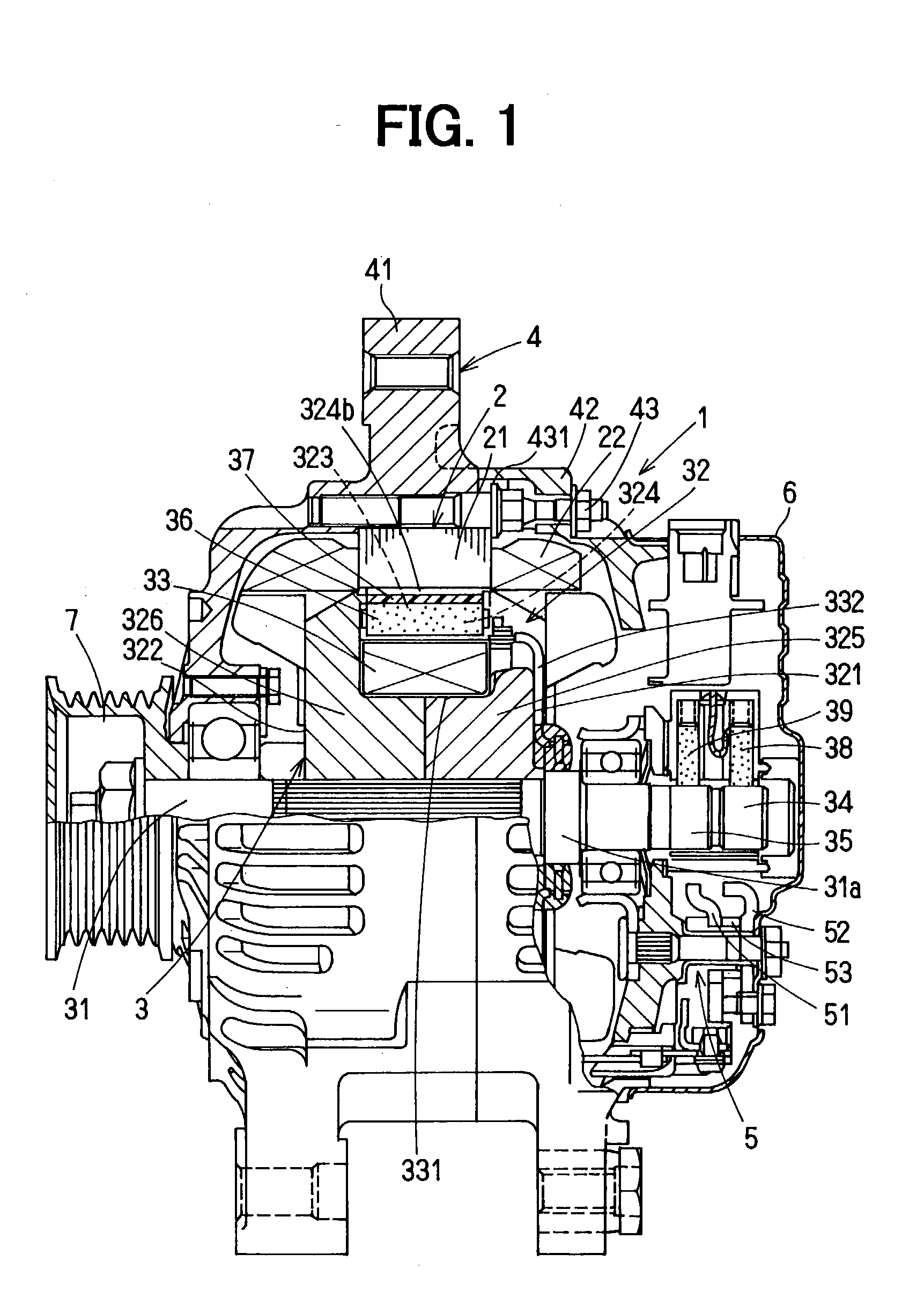
[0029] In the first embodiment, a rotating electric machine of the present invention is typically used for a vehicle alternating current (AC) generator 1. As shown in FIG. 1, the vehicle alternating current (AC) generator 1 according to the first embodiment includes a stator 2, a rotor 3, a housing 4, a rectifying unit 5, a cover 6, a pulley 7 and the like. The stator 2 includes a stator core 21 and stator coils 22, and is supported by the housing 4. The stator core 21 is formed by stacking plural thin steel plates, and has plural slots (not shown) in its inner side surface. The stator coils 22 are inserted into the plural slots, and an AC voltage is generated in the stator coils 22 by rotation of a rotor 3.
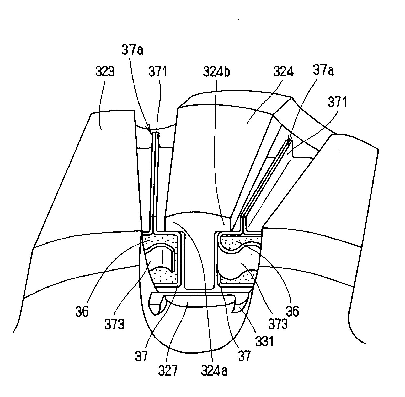
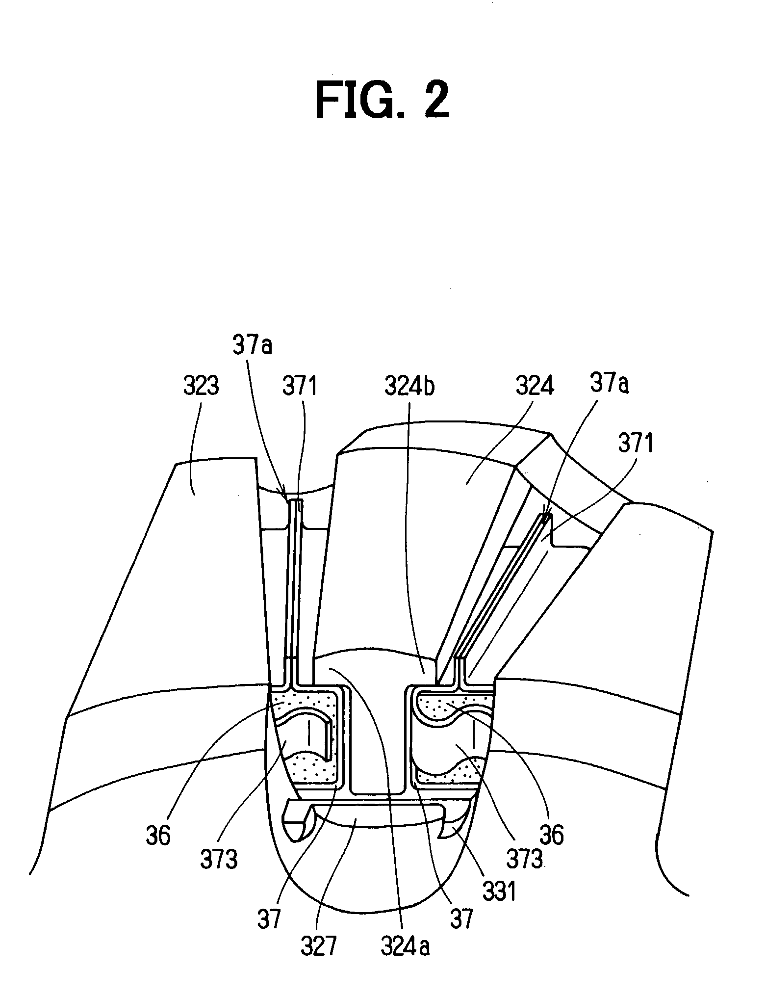
[0030] The rotor 3, shown in FIGS. 1, 2, rotates integrally with a shaft 31. The rotor 3 includes pole cores 32, field coils 33, two slip rings 34, 35, sixteen permanent magnets 36, magnet holders 37 and the like. One end of the shaft 31 is connected to t...
second embodiment
[0045] (Second Embodiment)
[0046] As shown in FIG. 6, in the second embodiment, the join portion 371 of the magnet holder 37 is fastened by pressing in place of the welding in the first embodiment. In the second embodiment, description of the same parts as in the first embodiment will be omitted, and only different parts will be described. At first, a single non-magnetic plate is bent so that the magnet holder 37 has a space in which the permanent magnet 36 can be fitted. Further, the two ends of the non-magnetic plate are joined, and are fastened by pressing, so that the join portion 371 is formed. Similarly to the above-described first embodiment, the join portion 371 protrudes from the radial outer surface of the magnet holder 37 to form the protrusion 37a. Specifically, one end portion of the non-magnetic plate in the join portion 371 is bent to form an insertion portion, and the other end portion thereof is inserted into the insertion portion. Thereafter, the join portion 371 is...
third embodiment
[0048] (Third Embodiment)
[0049] As shown in FIGS. 7A, 7B, in the third embodiment, the magnet holder 37 is different from that in the first embodiment. In the third embodiment, description of the same parts as in the first embodiment will be omitted, and only different parts will be described. As shown in FIG. 7B, the magnet holder 37 is formed so that its cross-section in a direction perpendicular to its longitudinal direction has an approximately U-shape. As shown in FIGS. 7A, 7B, one of longitudinal-extending surfaces protrudes at a circumferential center by pressing in its vertical direction, thereby forming a protrusion portion 376. That is, the radial outer side surface of the magnet holder 37 protrudes radial outside at a center portion in the circumferential direction.
[0050] Therefore, as in the first embodiment, the radial thickness of the radial outside surface of the magnet holder 37 increases, the rigidity of the radial outside surface at the circumferential center can b...
PUM
 Abstract
Description
Claims
Application Information