Electrical machine

a technology of electric machines and motors, applied in the direction of magnetic circuit rotating parts, magnetic circuit shape/form/construction, cooling/ventilation arrangement, etc., can solve the problems of synchronous generators that cannot meet the needs of synchronous generators, machine incurs net loss of flux, and line voltage total harmonic distortion (thd) will be worsened instead of being improved, so as to achieve optimal armature reaction compensation

Active Publication Date: 2019-05-23
ROLLS ROYCE PLC
View PDF0 Cites 0 Cited by
  • Summary
  • Abstract
  • Description
  • Claims
  • Application Information

AI Technical Summary

Benefits of technology

[0006]It would be desirable to provide mo

Problems solved by technology

Due to this effect, the machine incurs a net loss of flux.
Similar problems can be encountered with synchronous generators.
However, this approach has a disadvantage in that if the magnets are not located at the correct positions and/or are too powerful, the line voltage total harmonic distortion (THD) will be worsened instead of being improved.
However, other unidirectional rotational motoring/generating appl

Method used


Image

  • Electrical machine
  • Electrical machine
  • Electrical machine

Examples


Embodiment Construction

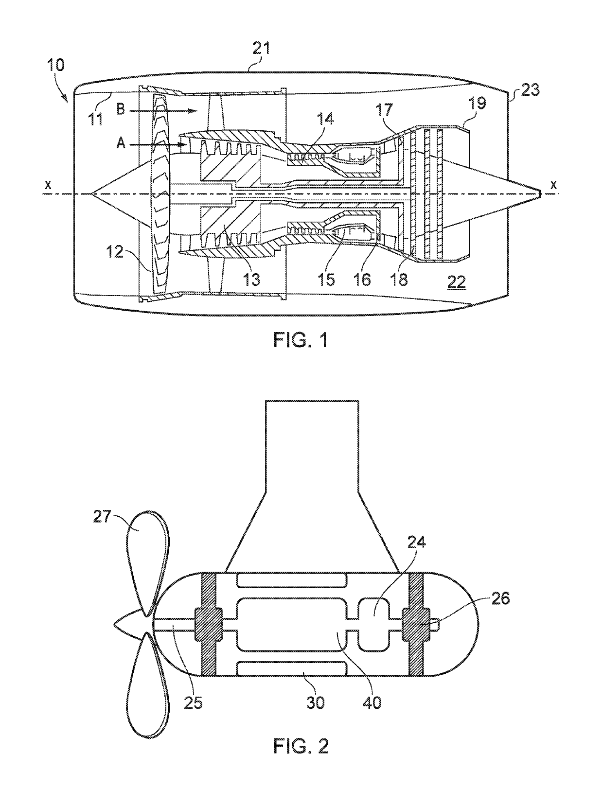
[0036]With reference to FIG. 1, a ducted fan gas turbine engine is generally indicated at 10 and has a principal and rotational axis X-X. The engine comprises, in axial flow series, an air intake 11, a propulsive fan 12, an intermediate pressure compressor 13, a high-pressure compressor 14, combustion equipment 15, a high-pressure turbine 16, an intermediate pressure turbine 17, a low-pressure turbine 18 and a core engine exhaust nozzle 19. A nacelle 21 generally surrounds the engine 10 and defines the intake 11, a bypass duct 22 and a bypass exhaust nozzle 23.

[0037]During operation, air entering the intake 11 is accelerated by the fan 12 to produce two air flows: a first air flow A into the intermediate-pressure compressor 13 and a second air flow B which passes through the bypass duct 22 to provide propulsive thrust. The intermediate-pressure compressor 13 compresses the air flow A directed into it before delivering that air to the high-pressure compressor 14 where further compres...


PUM


Abstract

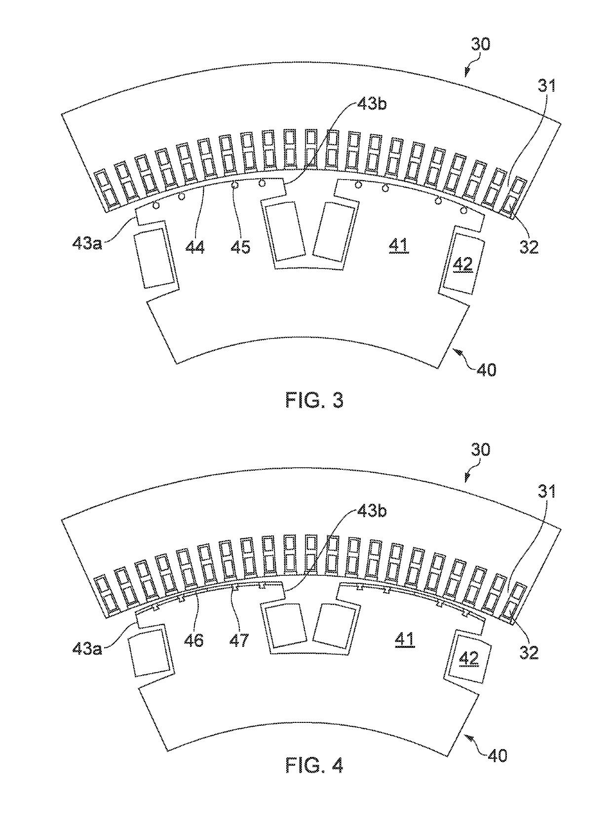
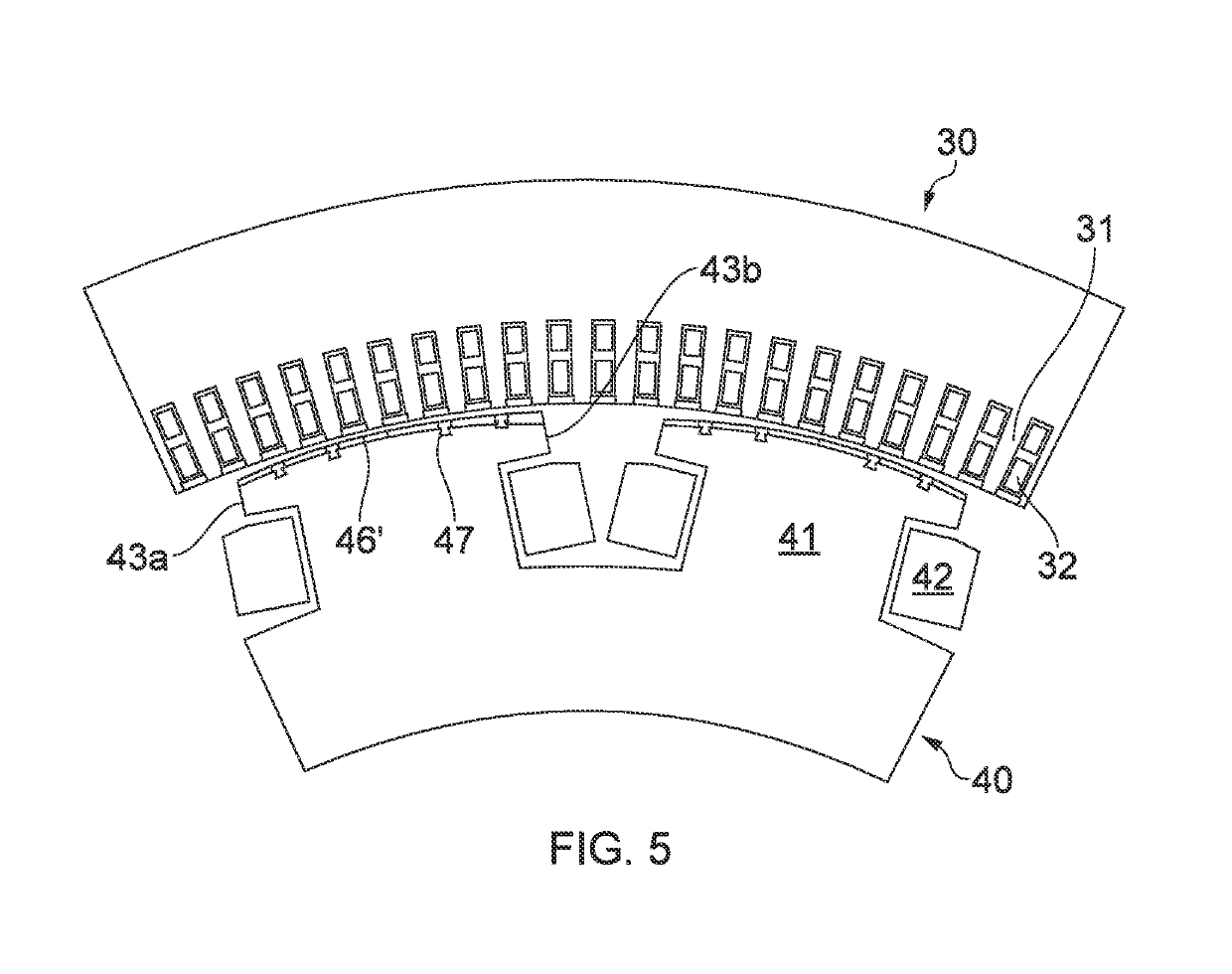
A synchronous electrical machine includes a stator having a circumferential row of teeth carrying stator windings. The electrical machine further includes a coaxial rotor having a circumferential row of poles carrying field windings. Each pole has first and second side flanks and a tip surface which extends continuously there between to form an air gap to the teeth of the stator. On a transverse cross-section through the machine, one of the side flanks forms a leading edge of the pole, and the other side flank forms an opposite, trailing edge of the pole. Each pole carries a row of permanent magnets which extends across the tip surface from one of the side flanks to the other side flank, the permanent magnets compensating for armature magnetic reaction. The radial thickness of the permanent magnets increases smoothly with progressive distance across the tip surface from one of the side flanks to the other side flank.

Description

CROSS-REFERENCE TO RELATED APPLICATIONS[0001]This application is based upon and claims the benefit of priority from British Patent Application No. GB 1719429.1, filed on 23 Nov. 2017, the entire contents of which are incorporated by reference.BACKGROUNDTechnical Field[0002]The present disclosure relates to an electrical machine having means for compensating for armature magnetic reaction.Description of the Related Art[0003]Most synchronous motors are designed to operate at unity power factor. At unity power factor, the cross-magnetizing effect (armature magnetic reaction) on the air gap flux is at its strongest, with the leading edge of the pole being partly-magnetized and the trailing edge partly-demagnetized. Due to this effect, the machine incurs a net loss of flux.[0004]Similar problems can be encountered with synchronous generators.[0005]For electrical machines that rotate in a preferred direction, armature reaction mitigation schemes can be employed. One such scheme is to moun...

Claims


Application Information

Patent Timeline
IPC IPC(8): H02K23/22H02K3/16H02K1/27H02K1/16
CPCH02K23/22H02K3/16H02K1/278H02K1/165H02K1/223H02K9/10H02K9/16H02K2201/03
Inventor CHONG, ELLIS F HRAMAKRISHNA, SHANMUKHATSENG, KING JETCHU, KIN HEY
Owner ROLLS ROYCE PLC
Why Eureka
Try Eureka