Method and apparatus for identifying one or more devices having faults in a communication loop

a technology of fault detection and communication loop, applied in the field of fault detection of one or more devices, can solve the problems of other devices failing completely, system devices failing to operate according to specified standards of operation, and no function at all

Active Publication Date: 2004-02-26
NETWORK APPLIANCE INC
View PDF4 Cites 54 Cited by
  • Summary
  • Abstract
  • Description
  • Claims
  • Application Information

AI Technical Summary

Problems solved by technology

Occasionally, devices of the systems fail to operate according to specified standards of operation.
Other devices fail completely and do not function at all, also known as catastrophic failures.
When a device is not fully operational or when the device fails completely, the device may impede the operability of the overall system.
For example, a failed storage device, such as a computer disk drive, in the storage system may disrupt operations of the other storage devices in the storage system by impeding communications through the FC loop.
A failed device, such as the storage device, connected to the FC loop causes the FC loop to become completely non-functional.
When a device is failing and disrupting operations of the system, the device is typically replaced with another.
While the failing devices are at times relatively simple to replace, identification of the failing device is much more difficult.
In the storage system, if one computer disk fails to function, the entire FC loops becomes non-functional and, as such, so may the storage system.
However, identifying the failed or failing computer disk(s) is a "trial and error" method as presently practiced in the art.
Identifying a failed or failing device through trial and error is an arduous task, particularly so when the system includes many devices, such as the storage system with hundreds of computer disks.
The entire process of removing each device until the failed or failing device is found and reengaging the incorrectly removed devices creates large periods of "down time".
Many systems cannot afford the luxury of having such a down time.
The central processing system relies heavily on a storage system to maintain data on the traffic and cannot have any portion of the overall system down for any observable length of time.
A failed storage system in the traffic management system could create catastrophic collisions within the traffic.
Since any one device may disrupt operability of the system, a connection processor may be communicatively connected to the decision module for bypassing the devices having the faults.

Method used


Image

  • Method and apparatus for identifying one or more devices having faults in a communication loop
  • Method and apparatus for identifying one or more devices having faults in a communication loop
  • Method and apparatus for identifying one or more devices having faults in a communication loop

Examples


Embodiment Construction

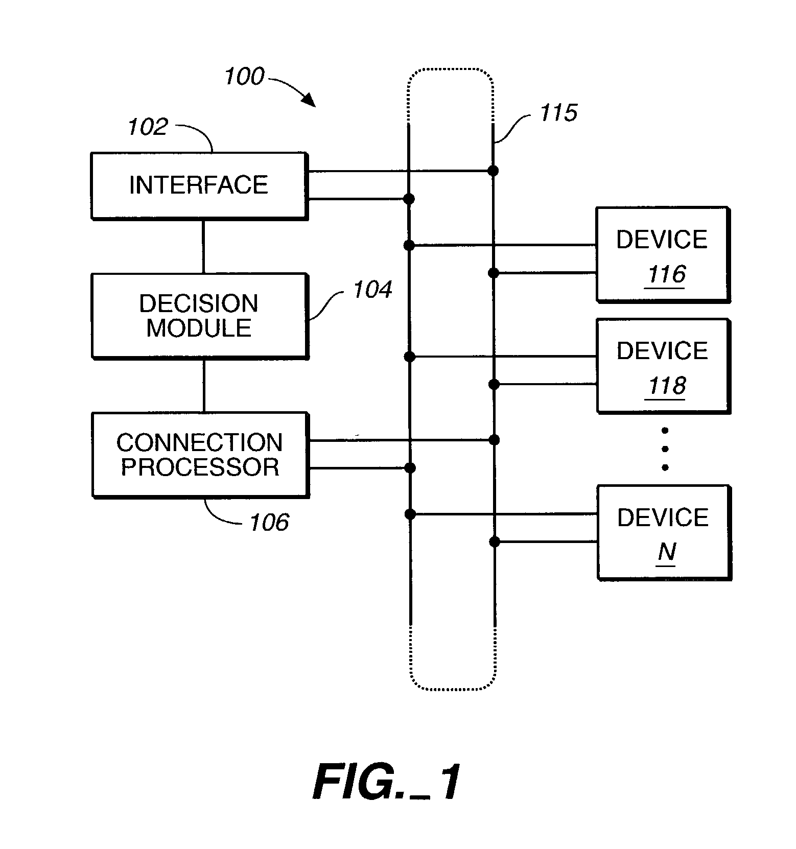
[0024] FIG. 1 is a block diagram illustrating an exemplary preferred embodiment of the invention.

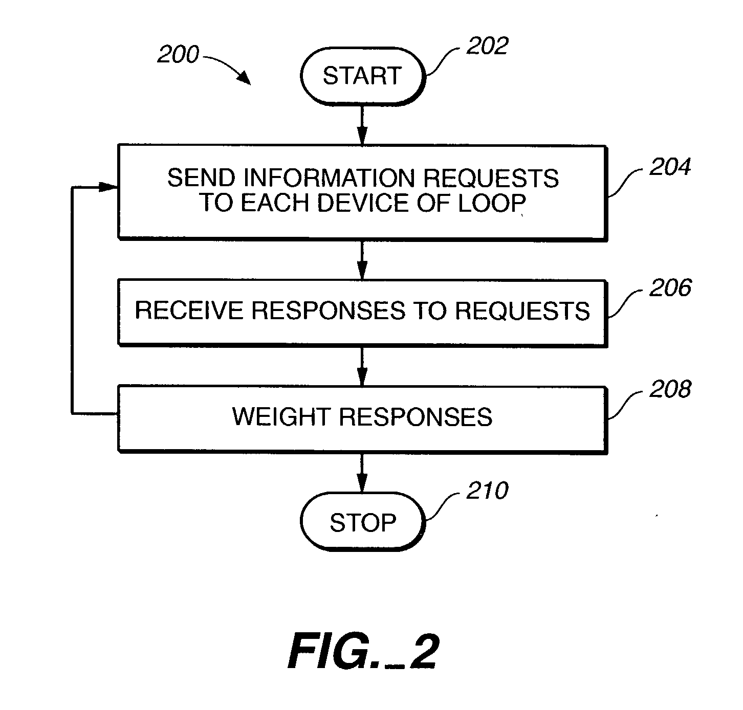
[0025] FIG. 2 is a flow chart diagram illustrating an exemplary preferred operation of the invention.

[0026] FIG. 3 is a flow chart diagram illustrating another exemplary preferred operation of the invention.

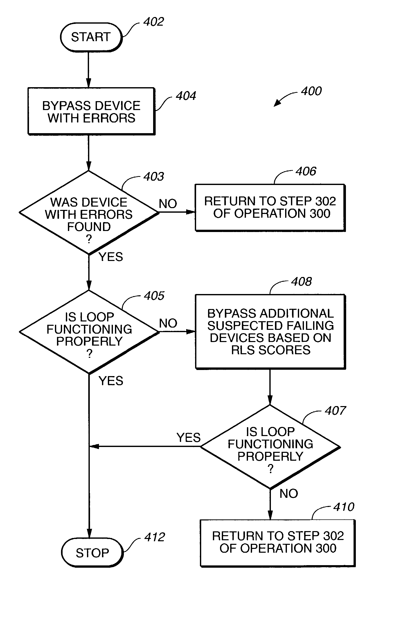
[0027] FIG. 4 is a flow chart diagram illustrating an exemplary preferred operation of the invention.

[0028] While the invention is susceptible to various modifications and alternative forms, a specific embodiment thereof has been shown by way of example in the drawings and will herein be described in detail. Those skilled in the art will appreciate that the features described below can be combined in various ways to form multiple variations of the invention. As a result, the invention is not limited to the specific examples described below, but only by the claims and their equivalents.

[0029] With reference now to the figures and in particular with reference to FIG. 1, an exemplary pre...


PUM


Abstract

A system identifies one or more devices having faults in a communication loop. The system includes an interface, a decision module, and a connection processor. The interface is configured for sending requests for information to each device of the communication loop and for receiving responses to the requests. The devices may include computer disk drives for use in a storage system. The requests may include Read-Link Status (RLS) commands sent to the computer disk drives. The RLS commands may provide diagnostics of the disk drives connected to the loop. The decision module is communicatively connected to the interface for weighting the responses of each device to identify the devices having the faults. The responses may be weighted based on the relative potential for disrupting operability of the system. The communication loop may include an FC loop that allows communications between a host system and the computer disk drives.

Description

[0001] 1. Field of the Invention[0002] The present invention is generally directed toward fault detection of one or more devices. More specifically, the present invention relates to identifying faulty devices connected to a storage system communication loop such that the devices may be bypassed.[0003] 2. Discussion of Related Art[0004] Many systems functionally include a variety of devices in order to operate. For example, a storage system may include multiple storage devices for storing large amounts of data. In the storage system example, the storage devices and storage controllers are often interconnected through a Fibre Channel (FC) loop. The storage system may be communicatively connected to a host system, such that the host system sends requests to the storage devices through an FC loop. In an FC loop, all devices are interconnected in a "daisy-chained" fashion--each to the next device in a continuous loop topology.[0005] Occasionally, devices of the systems fail to operate ac...

Claims


Application Information

Patent Timeline
Patent Type & Authority Applications(United States)
IPC IPC(8): H04L1/24
CPCH04L1/243H04L43/0817H04L41/06H04L12/437
Inventor RIEDL, DANIEL A.LYNN, JAMES A.GITCHELL, ANTHONY D.
Owner NETWORK APPLIANCE INC
Why Eureka
Try Eureka