Attachment for a rotary milking platform

a technology of rotary milking platform and attachment plate, which is applied in the field of attachment plate for rotary milking platform, can solve the problems of inconvenient operation, inconvenient operation, and inability to make sense ergonomically, and achieve the effect of reducing previous problems of uneven milking, saving dairy farmers a large amount of money, and adding to the comfort of the milking process for cows

Inactive Publication Date: 2004-03-18
DELAVAL HLDG AB
View PDF7 Cites 0 Cited by
  • Summary
  • Abstract
  • Description
  • Claims
  • Application Information

AI Technical Summary

Benefits of technology

[0032] In some embodiments the position of the spacers may be near the edge of each stall or bail on the platform. The position of the spacers defines a space in between which the hoses from the clusters can effectively float. This ability for the hoses to move within the elongate aperture (as opposed to a tight hole in a platform) means that the natural inclination of the hoses and therefore the cluster attached to the hoses will be to align with the cows udder.
[0033] This minimises previous problems with uneven milking and cup slip as well as add to the comfort of the milking process for cows.
[0034] Further, this design enables the ready incorporation of a cluster arm which can support the cluster removal. These automation obviously assists the whole milking process.
[0035] Further advantages of this configuration allows the placement of the milking clusters where they cannot entangle with the cows legs and in a position which is ergonomically of benefit to the farmers. For example, after milking, the clusters may be moved within the elongated aperture to the side of the bail allowing ready exit of the cow from the bail without entangling the clusters.
[0036] This attachment may be configured to enable it to be retrofitted to existing rotary milking platforms. This enables all the advantages as herein described to be conferred to those consumers with existing rotary milking platforms undertaking a major refit of their milking sheds, or completely replacing their rotary milking platforms. This has an additional advantage of saving the dairy farmer a large amount of money on the upgrade of their rotary milking platform.

Problems solved by technology

The placement of the milk cluster (teat cups and hosing) in relation to the rotary platform is of considerable importance as wrong placement can lead to inefficiencies.
Unfortunately the problem with this arrangement is that the cows often entangle with the clusters on the deck or platform.
So this is obviously a unsatisfactory situation.
This requires the farmer to bend underneath the platform, which is inconvenient and does not make sense ergonomically.
Another problem with this particular system is that the hose rubbers often cut in the process of moving them.
A problem with this system is quite often the drag on the hoses from the hole causes the cups to pull off the cows.
This problem has been excaberated with the current trend of having concrete platforms.
However, concrete is thicker than steel and thus the problems of passing of a hose through a hole in a concrete platform are greater than with steel.
Otherwise, uneven milking or squawking can occur.
The thicker concrete platform creates drag on the hoses and therefore the clusters can be skewed.

Method used


Image

  • Attachment for a rotary milking platform
  • Attachment for a rotary milking platform

Examples


Embodiment Construction

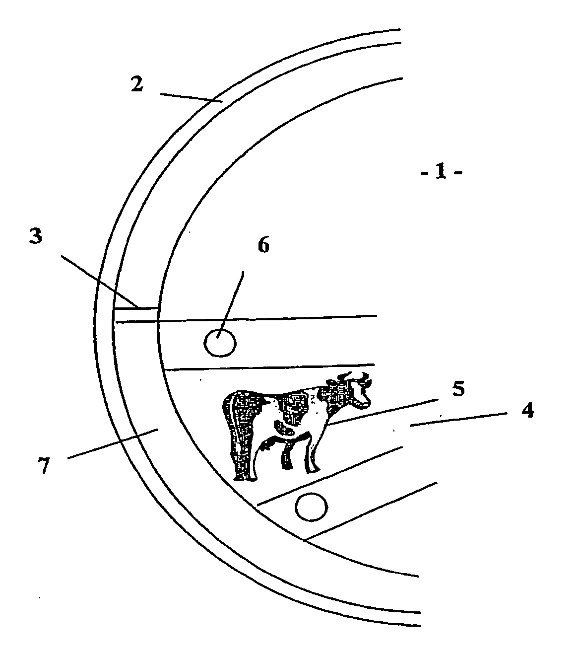
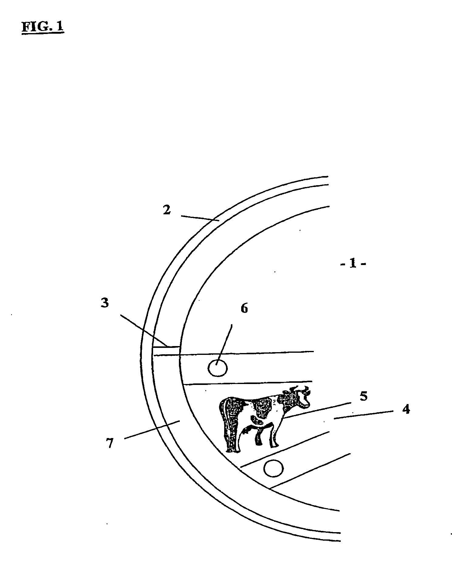
[0039] FIG. 1 illustrates a rotary platform generally indicated by arrow 1 which incorporates a cluster ring 2.

[0040] The cluster ring 2 is connected to the platform 1 via spacers 3. Spacers 3 are positioned at the side of each of the bails 4 where the animals 5 are milked.

[0041] Alongside each bail 4 is a bail dummy 6.

[0042] The positioning of the spacers 3 can depend upon the direction of rotation of the platform. If the platform rotates clockwise as in the present invention, then the spacers 3 will be positioned to the left of the bail dummy as shown. Alternatively, if the platform rotates anti-clockwise, then the spacer for a particular bail placed to the right of the bail dummy. The placement of spacers determines the furthest that the hoses of the milking cluster can move in one direction.

[0043] It can be seen that the present invention can enable the hosing from the milking cluster to effectively float in the aperture 7 created between the ring 2 and the platform 1. This ensu...


PUM


Abstract

An attachment (2) for a rotary milking platform (1) characterised in that the attachment (2) is in the form of a frame surrounding at least one elongated aperture (7) positioned on or near the circumference of the rotary platform (1), the frame connected to the platform (1) by spacers (3), wherein the elongated aperture (7) can accommodate hosing associated with milking equipment.

Description

[0001] This invention relates to improvements to milking systems.[0002] Reference throughout the specification shall be made to the use of the present invention in relation to milking systems on rotary platforms. However, it should be appreciated that it is possible that the present invention can be applied to other systems.[0003] Reference throughout the specification should be made to the animal being milked as a cow, although again it should be appreciated that the principles of the present invention could be applied to animals other than cows, which is given by way of example only.[0004] Typical rotary platforms work by having a cow entering the platform at a fixed entry point after which the farmer places teat cups onto the cows. Typically the cow travels one revolution (sometimes two) of the platform before its teat cups are removed and the cow departs via a fixed exit point. As can be appreciated, the teat cups and associated hosing travel around with the cow and the platform...

Claims


Application Information

Patent Timeline
Patent Type & Authority Applications(United States)
IPC IPC(8): A01K1/12
CPCA01K1/126
Inventor BATTERSBY, BRUCEKERR, MARY
Owner DELAVAL HLDG AB
Why Eureka
Try Eureka