
Power supply apparatus in electric vehicle

Inactive Publication Date: 2004-03-25
HONDA MOTOR CO LTD
View PDF2 Cites 39 Cited by
  • Summary
  • Abstract
  • Description
  • Claims
  • Application Information

AI Technical Summary

Benefits of technology

[0010] The present invention has been made in view of the above demand. It is an object of the present invention to provide a power supply apparatus in an electric vehicle for stabilizing a voltage generated on a power supply line by an electric motor and protecting system components from overcharging of a battery and a generated overvoltage, even when no electric power is supplied from the battery to a control means, or when the battery is removed.
[0014] According to the first feature, the control means is activated by the activating unit, even when no electric power is supplied from the battery to the control means, or when the battery is removed. Therefore, when no electric power is supplied from the battery to the control means or the battery is removed, the voltage on the power supply line, which is generated by the electric motor, is stabilized, and system components are protected from a generated overvoltage.
[0015] According to the second feature, the voltage on the power supply line can be stabilized when the control means closes the switch to connect the regenerative resistor.
[0016] According to the third feature, the voltage on the power supply line can be stabilized when the control means controls the drive means to stabilize the voltage on the power supply line.

Problems solved by technology

When the battery is removed or the switch is turned off, the voltage on the power supply line is not stabilized and increases, thus making it difficult to protect components (FETs, etc.) of the power supply apparatus.
Hei 5-49101, the control circuit is supplied with electric power from the battery at all times. The control circuit is not designed to prepare for the situation when the battery is removed or the switch is turned off.
Therefore, it is difficult to solve the above problems even if the disclosed arrangement is applied to an electric vehicle.

Method used


Image

  • Power supply apparatus in electric vehicle
  • Power supply apparatus in electric vehicle
  • Power supply apparatus in electric vehicle

Examples


Embodiment Construction

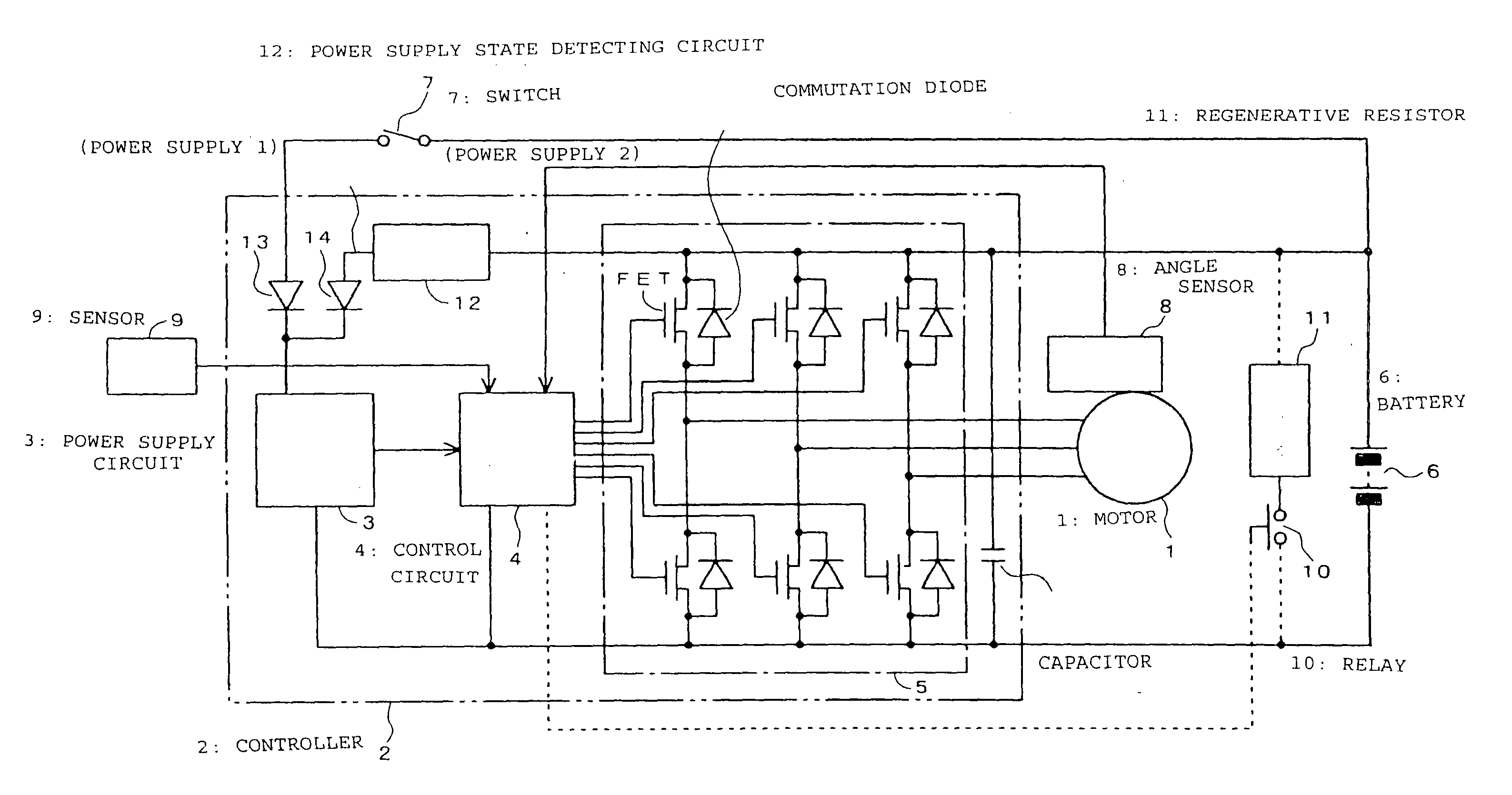
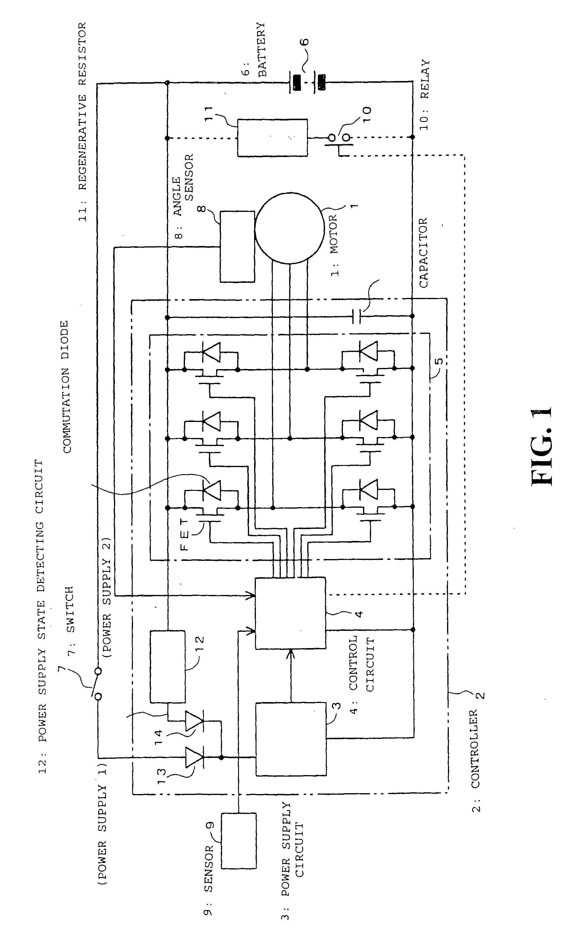
[0028] FIG. 1 is a block diagram of an embodiment of a power supply apparatus for an electric vehicle to which the present invention is applied. The power supply apparatus according to the present embodiment has a controller 2 for energizing a permanent-magnet brushless motor 1. The controller 2 has a power supply circuit 3, a control circuit 4, and a drive circuit 5. A switch 7 functions as a power supply switch for supplying electric power to the controller 2. When the switch 7 is turned on, electric power from a battery 6 is supplied through the switch 7, a diode 13, and the power supply circuit 3 to the control circuit 4, activating the control circuit 4.

[0029] The drive circuit 5 constitutes pairs of FETs and commutation diodes that are connected in a bridge. The control circuit 4 selectively energizes the FETs of the drive circuit 5 according to an output signal from an angle sensor 8 which detects an angular displacement of the motor 1, and controls currents of the FETs accor...


PUM


Abstract

A power supply apparatus for stabilizing a voltage generated on a power supply line by an electric motor, for preventing a battery from being overcharged, preventing an overvoltage from being generated, and protecting system components from an overvoltage, even when a battery is removed or no electric power is supplied from the battery to a control means. The apparatus includes a drive circuit for energizing a permanent-magnet brushless motor and a control circuit for controlling the drive circuit. A power supply state detecting circuit (activating unit) activates the control circuit depending on a voltage value on a power supply line of the motor. A voltage stabilizing means including a relay and a regenerative resistor stabilizes the voltage on the power supply line when the relay is opened and closed under the control of the control circuit. The voltage stabilizing means may include the drive circuit.

Description

[0001] The present application claims priority under 35 USC 119 to Japanese Patent Application No. 2002-249310 filed on Aug. 28, 2003, the entire contents thereof is hereby incorporated by reference.[0002] 1. Field of the Invention[0003] The present invention relates to a power supply apparatus in an electric vehicle such as a motor driven scooter, or the like. More particularly the present invention relates to a power supply apparatus in an electric vehicle for stabilizing a voltage generated on a power supply line by an electric motor, preventing a battery from being overcharged, preventing an overvoltage from being generated, and protecting system components from an overvoltage, even when no electric power is supplied from the battery to a control means for controlling the energization of the electric motor or the battery is removed.[0004] 2. Description of Background Art[0005] Motor driven scooters have an electric motor for rotating an axle, e.g., a permanent-magnet brushless m...

Claims


Application Information

Patent Timeline
IPC IPC(8): B60L7/22H02P3/18
CPCB60L7/22B60L11/1801B60L11/1803B60L11/1877B60L2200/12B60L11/007B60L2250/24B62K2202/00Y02T10/7005Y02T10/705B60L2220/44B60L50/20B60L50/51B60L50/53B60L50/66B62K2204/00Y02T10/70
Inventor HONDA, SOTOSHI
Owner HONDA MOTOR CO LTD
Learn More