
Electrophotographic apparatus

a technology of electrophotography and apparatus, applied in the field of electrophotography apparatus, can solve the problems of insufficient system for reproducing halftone images, complex apparatus, and increased cost of main body

Inactive Publication Date: 2004-03-25
CANON KK
View PDF18 Cites 13 Cited by
  • Summary
  • Abstract
  • Description
  • Claims
  • Application Information

AI Technical Summary

Benefits of technology

[0019] Another object of the present invention is to provide an image forming apparatus in which cleaning is stable without cleaning failures or the like for a long time.

Problems solved by technology

However, the system is insufficient for reproduction of a halftone image such as a photograph which is essential.
Consequently, the apparatus becomes complex, larger in size, and costs become higher for main body.
There has been a limit on improvement of cleaning performance only by a macro image ratio over all the images.
Consequently, there is a tendency that places in which transfer residual toner is generated in pixel units are numerous on a pixel center, while generation of transfer residual toner on a boundary in which pixels are adjacent to each other is limited.
Thus, an adhesive force of toner to the surface of the photosensitive drum per unit mass is increased to deteriorate cleaning performance of the surface of the photosensitive drum.
Additionally, as the toner particle diameter becomes smaller, toner flowability is deteriorated, and a great amount of additives is necessary.
Such a great amount of additives causes problems of wearing or chipping of the cleaning blade, and local line flaws on the surface of the photosensitive drum.
Consequently, there are problems of nonuniformity of a frictional force generated between the photosensitive drum and the cleaning blade in the longitudinal direction, which is influenced by the aforementioned nonuniformity of the transfer residual toner or the like; frequent occurrence of vibration and clashing of the cleaning blade, cleaning failures, cleaning blade reversal, etc. owing to a torque increase of the photosensitive drum which accompanies an increase of a blade pressing force; and a shortened life of the photosensitive drum because of hard wearing of the photosensitive drum.

Method used


Image

  • Electrophotographic apparatus
  • Electrophotographic apparatus
  • Electrophotographic apparatus

Examples


first embodiment

[0031] First Embodiment

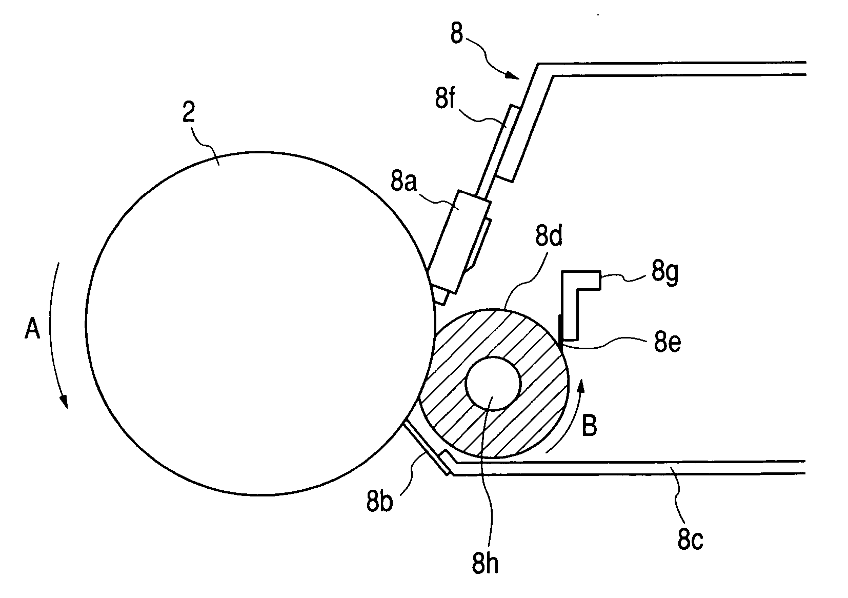
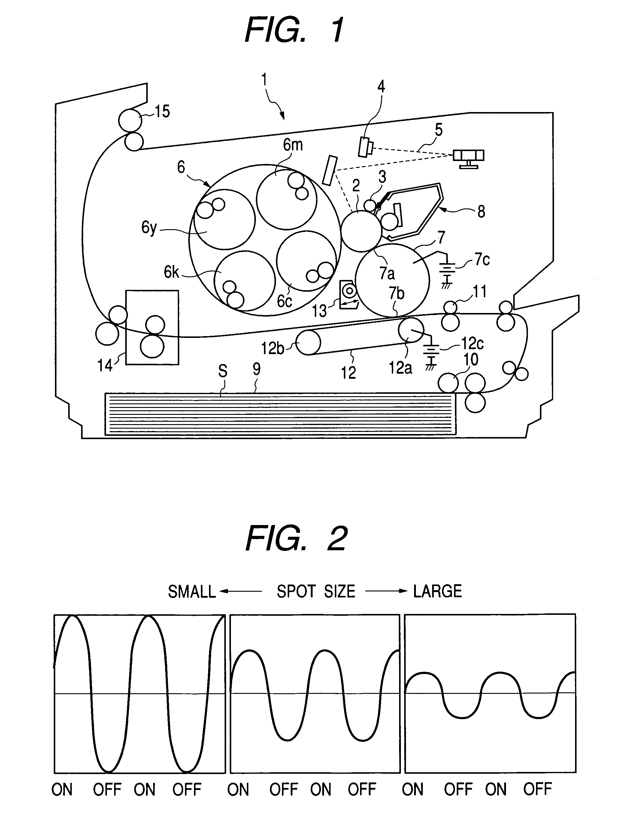
[0032] A first preferred embodiment of an image forming apparatus of the present invention will be described with reference to the drawings. FIG. 1 is a schematic constitutional view of the electrophotographic image forming apparatus of the embodiment.

[0033] Overall Constitution

[0034] An image forming apparatus 1 shown in FIG. 1 is a color copying machine of an electrophotographic system, which forms an image on a recording medium in accordance with an image signal sent from a not-shown computer or the like. A photosensitive member 2 of the image forming apparatus 1 is formed by coating a photosensitive material such as OPC of an outer diameter 62 mm on an outer peripheral surface of a cylinder substrate made of aluminum or the like.

[0035] The photosensitive member 2 is rotary-driven at a circumferential speed of 117 mm / sec, and uniformly charged to about -600 V as a dark portion potential VD by a charging roller 3 as contact charging means. Then, a laser osci...

second embodiment

[0114] Second Embodiment

[0115] As preferred image forming method and apparatus of the embodiment, a photosensitive member of a photoconductive layer (photosensitive layer) made of a non-single crystal material in which a silicon atom is a matrix, i.e., an amorphous silicon photosensitive member, is used as an electrophotographic photosensitive member. The amorphous silicon member is suitably used to achieve high durability and a long life because of its high wear resistance and limited changes in electrical characteristics (especially E-V characteristics) with passage of time. For the method and the apparatus of the embodiment for image formation, description of portions similar to those of the first embodiment is omitted. An outer dimension, a shape etc., of the photosensitive member are also similar to those of the first embodiment.

[0116] Photosensitive Member

[0117] FIGS. 7A and 7B show an example of an electrophotographic photosensitive member of the present invention. The electr...

third embodiment

[0122] Third Embodiment

[0123] The embodiment is different from the first embodiment in the following points. That is, a process speed is 400 mm / sec., a rotational direction of a fur brush is similar to the nip of the photosensitive drum, and it rotational speed is set to 100 rpm.

[0124] The inventors conducted an experiment of passing 100 thousand sheets in which at the above setting, resolution was set to 800 dpi, i.e., 1 pixel area S=1.0.times.10.sup.-3 (mm.sup.2 / dot) was set, a brush density was set to D=186 (number / / mm.sup.2), S.times.D=0.186 was set, and a thickness of a brush fiber was changed to 10 to 50 .mu.m. Table 1 shows a result of the experiment.

1 TABLE 1 Brush 15 20 30 50 65 80 thickness (.mu.m) Result of X .largecircle. .largecircle. .largecircle. X X sheet passage

[0125] Thus, even if D.times.S.gtoreq.0.06 which is a product of the cleaning density D and 1 pixel area S, and D.ltoreq.200 are satisfied, according to the embodiment, at a high speed and at high resolution,...


PUM


Abstract

An electrophotographic apparatus comprises a photosensitive member, exposing means, and cleaning means for cleaning a residual developer from the photosensitive member, which comprises a cleaning brush brought into contact with the photosensitive member. In this case, if a brush density of the cleaning brush is D (number / mm<2>), and an area of a pixel of an electrostatic image is S (mm<2> / dot), DxS>=0.06 and D<=200 are satisfied. Thus, an image forming apparatus is provided, in which cleaning stability is improved by uniformly scraping off and dispersing the transfer residual developer from the photosensitive member.

Description

[0001] 1. Field of the Invention[0002] The present invention relates to an electrophotographic apparatus such as a copying machine, a printer or a facsimile which forms an image by using an electrophotographic system, and more particularly to an image forming apparatus which has a cleaning member for cleaning residual toner left on a surface of a photosensitive member.[0003] 2. Description of the Related Art[0004] Generally, in an image forming apparatus such as a copying machine, a printer or a facsimile which records an image on a recording medium such as paper, an electrophotographic system is adopted as a system to record the image on the recording medium. In the electrophotographic system, a photosensitive drum as a photosensitive member, on a surface of which a photosensitive substance is coated, is used as an image bearer (or image carrier member). First, after the surface of the photosensitive drum is uniformly charged, the surface of the photosensitive drum is irradiated wi...

Claims


Application Information

Patent Timeline
Patent Type & Authority Applications(United States)
IPC IPC(8): G03G5/08G03G5/147G03G9/08G03G21/00G03G21/10
CPCG03G2221/0089G03G21/0035
Inventor ITO, MASAHIRO
Owner CANON KK
Learn More