Control unit for spark ignition-type engine

Inactive Publication Date: 2004-04-01
MAZDA MOTOR CORP
View PDF7 Cites 14 Cited by
  • Summary
  • Abstract
  • Description
  • Claims
  • Application Information

AI Technical Summary

Problems solved by technology

In such an engine, however, only an ordinary three-way catalyst used to purify exhaust gas (having a high capability to remove HC, CO and NO.sub.x at and around a stoichiometric ratio) is inadequate to remove NO.sub.x at the time of a lean operation.

Method used


Image

  • Control unit for spark ignition-type engine
  • Control unit for spark ignition-type engine
  • Control unit for spark ignition-type engine

Examples


Embodiment Construction

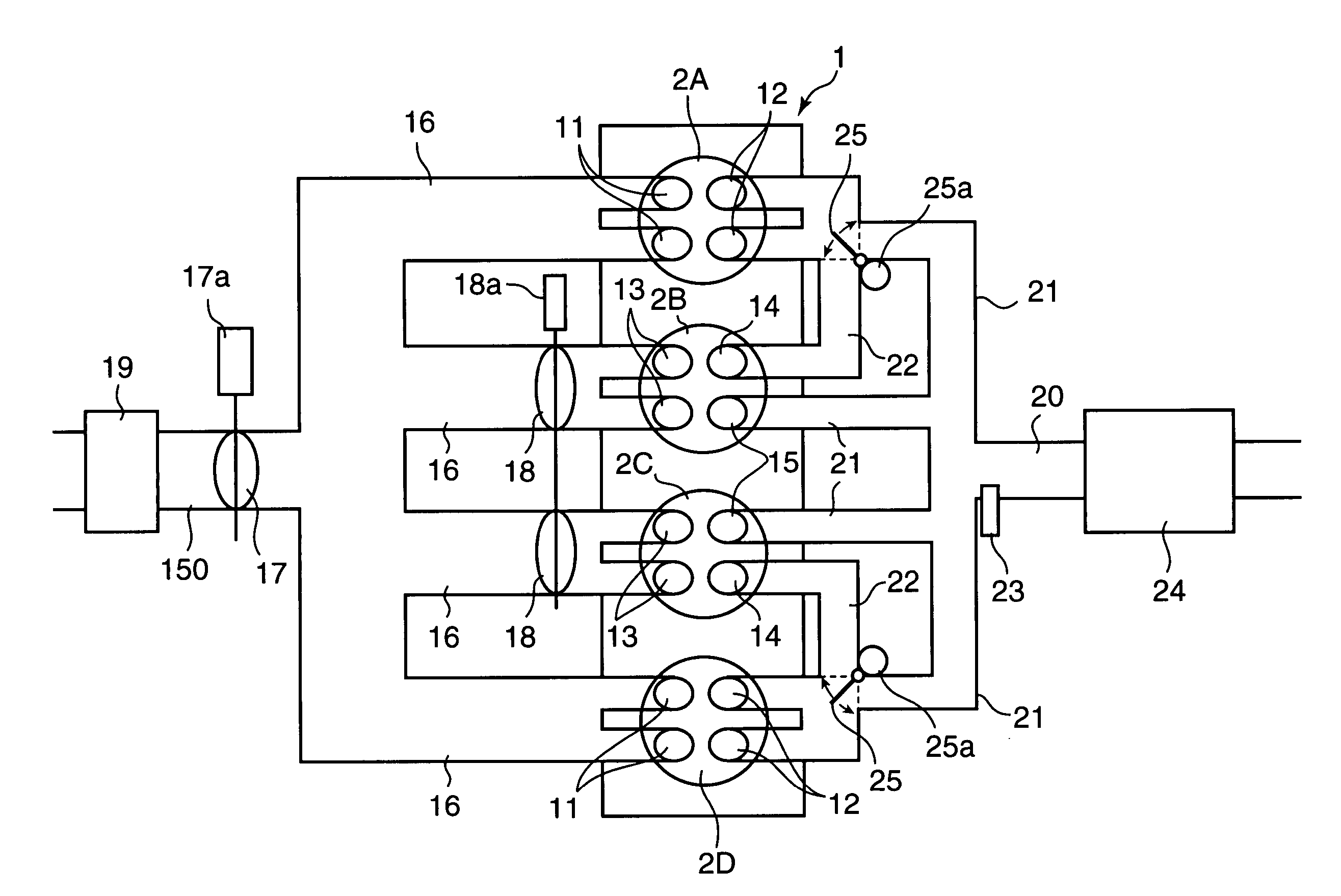
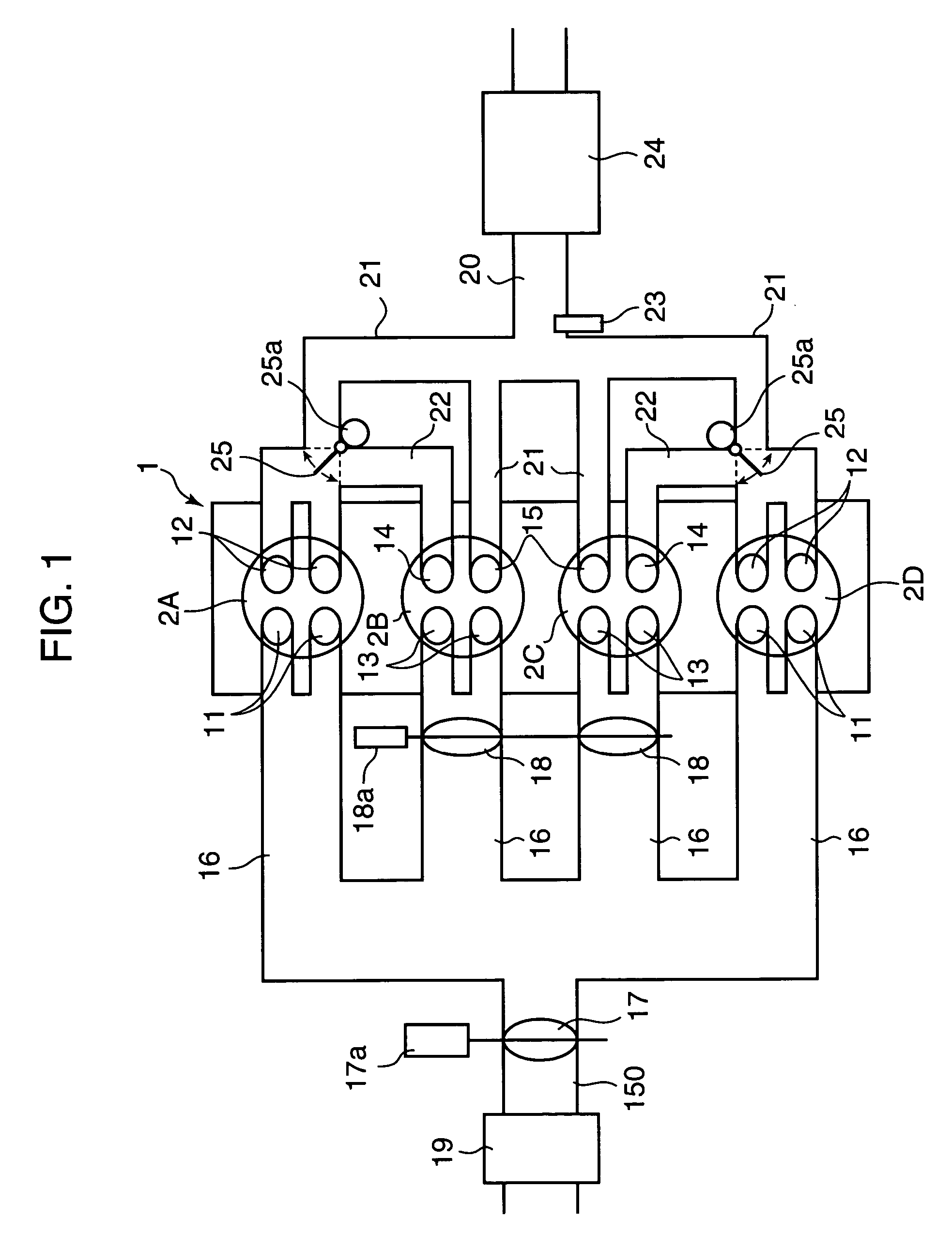
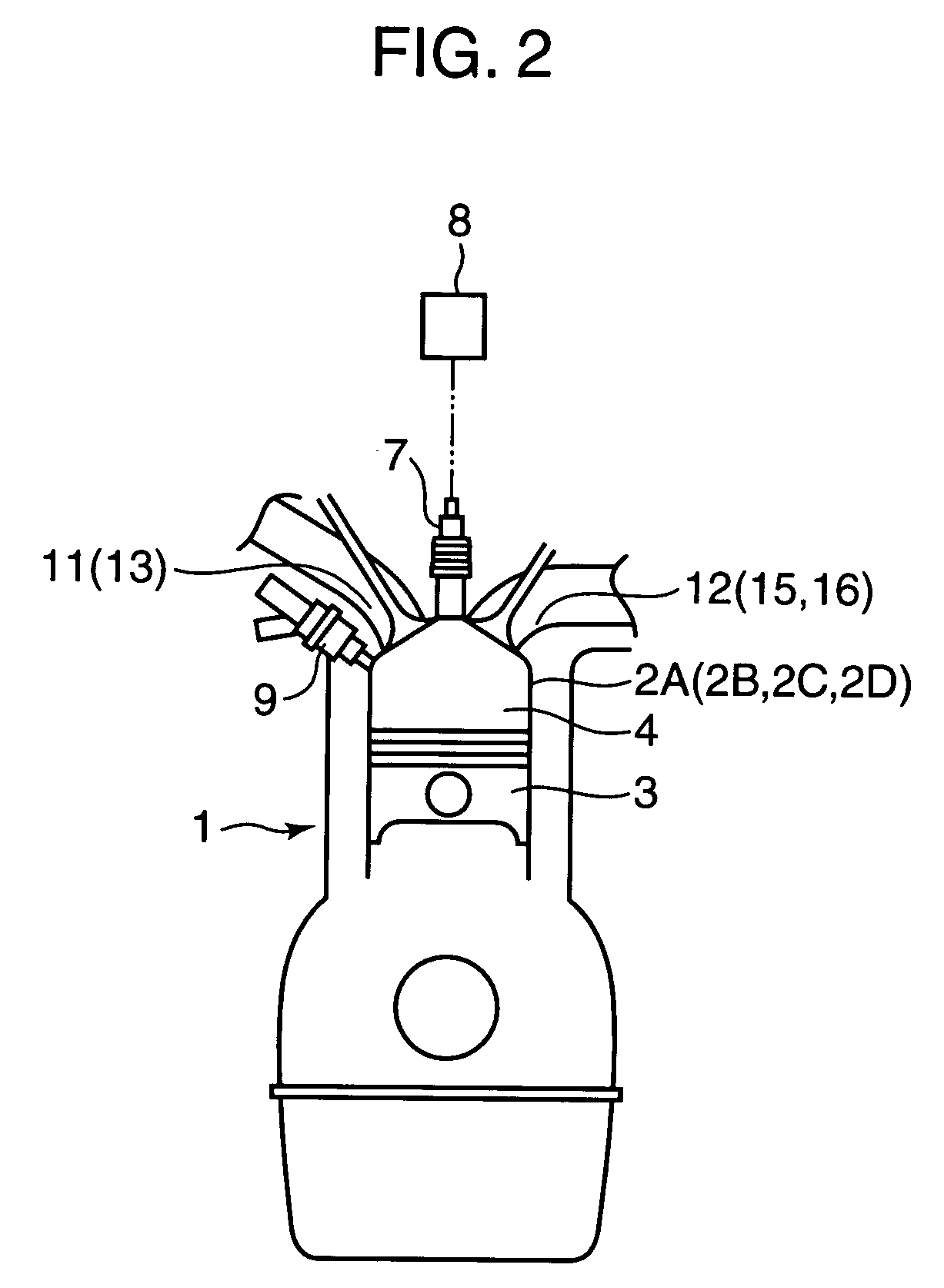
[0028] FIG. 1 and FIG. 2 show a rough configuration of the engine according to an embodiment of the present. In these figures, an engine main body 1 includes a plurality of cylinders. Specifically, it includes four cylinders 2A to 2D according to the embodiment shown in the figures. A piston 3 is inserted into each cylinder 2A to 2D. A combustion chamber 4 is formed over the piston 3.

[0029] A spark plug 7 is disposed at the top part of the combustion chamber 4 formed in each cylinder 2A to 2D. The tip of the spark plug 7 faces the inside of the combustion chamber 4. To the spark plug 7 is connected an ignition control circuit 8 which can control ignition timing through its electronic control.

[0030] At a side part of the combustion chamber 4, a fuel injection valve 9 is provided which injects fuel directly into the combustion chamber 4. The fuel injection valve 9 houses a needle valve and a solenoid (not shown). A pulse signal is inputted in the fuel injection valve 9 from a fuel-inj...


PUM


Abstract

In a partial load range of the engine, control of the flowing state of sucked and discharged gas is executed between a pair of cylinders, an exhaust stroke of one of the cylinders overlapping with an intake stroke of the other, so that burnt gas discharged from preceding cylinders 2A, 2D on the exhaust-stroke side is introduced, in a state where it has been discharged, through an inter-cylindrical gas passage 22 into following cylinders 2B, 2C on the intake stroke side. In a higher load range than the partial load range, control is executed so that a fresh-air introducing valve 18 disposed in a fresh-air introduction passage of the following cylinders 2B, 2C is opened, both the burnt gas and fresh air are introduced into the following cylinders 2B, 2C, and fuel is supplied to conduct combustion in the following cylinders 2B, 2C.

Description

[0001] 1. Field of the Invention[0002] This invention relates to a control unit for a spark ignition-type engine, more specifically, a control unit for controlling the state of combustion in each cylinder of a multi-cylinder engine which is capable of improving fuel efficiency and exhaust emissions.[0003] 2. Description of the Related Art[0004] In a conventionally-known spark ignition-type engine which is capable of improving fuel efficiency, combustion is conducted with the air-fuel ratio of a mixture inside each cylinder being kept at a lean air-fuel ratio higher than a stoichiometric ratio. Particularly, in an engine which is provided with a fuel injection valve for injecting fuel directly into a combustion chamber, stratified charge combustion is conducted by injecting fuel from the fuel injection valve in a lower speed & lower-load range or the like at a compression stroke, leading to the realization of a super-lean burn (for example, refer to Japanese Patent Laid-Open No. 10-2...

Claims


Application Information

Patent Timeline
Patent Type & Authority Applications(United States)
IPC IPC(8): F02B15/00F02B1/04F02B1/12F02B75/12F02D9/02F02D9/04F02D13/02F02D21/08F02D37/02F02D41/00F02D41/02F02D41/04F02D41/30F02D41/34F02D43/00F02D45/00F02F1/42F02M25/07
CPCF01L2201/00Y02T10/42F02B1/04F02B1/12F02B2075/125F02D9/04F02D13/0276F02D37/02F02D41/0002F02D41/006F02D41/008F02D41/028F02D41/1454F02D41/3023F02D41/3035F02D2041/002F02F1/4214F02M25/0719F02M25/0749Y02T10/18Y02T10/14F01L2800/00F02M26/16F02M26/43Y02T10/12Y02T10/40
Inventor HITOMI, MITSUOASANOMI, KOUJINISHIMOTO, TOSHIAKIYAMAUCHI, TAKETOSHI
Owner MAZDA MOTOR CORP
Why Eureka
Try Eureka