Laminated sheet manifold for microchannel heat exchanger

a microchannel heat exchanger and manifold technology, applied in the field of heat exchangers, can solve the problems of inability to accept further, non-uniform temperature distribution, and hot spots, and achieve the effect of facilitating the use of the heat exchanger

Active Publication Date: 2009-08-27
VERTIV CORP
View PDF29 Cites 67 Cited by
  • Summary
  • Abstract
  • Description
  • Claims
  • Application Information

AI Technical Summary

Benefits of technology

[0015]In some embodiments, the first and second manifolds form flow passageways with two heat exchanger cores. The two manifolds can supply a single fluid flow through both cores or separate fluid flows through each core that do not intermix. The use of a single set of manifolds to provide flow passageways with two cores can provide a more compact heat exchanger utilizing multiple cores. The use of multiple cores may also facilitate the use of the heat exchanger as an evaporator or condenser and the sizes of the tubes in the cores can be designed to accommodate single-phase and multi-phase flow.

Problems solved by technology

In air-cooling applications, this might mean positioning the air-to-coolant heat exchanger in the computer rack between card chassis as an “intercooler.” When the heat exchanger is so close to the heat source, however, hot spots on the electronic equipment can cause a non-uniform temperature distribution, in any coordinate direction, across the heat exchanger.
The hot spots in the coil limit the ability to accept further thermal load, thus creating hot spots in the exterior airflow to be cooled, and further creating hot spots in the electronics in the downstream airflow path.
The use of round piping, however, can require that the microchannel tubing intrudes into the cavity within the round piping a significant amount.
Additionally, the large intrusion can limit the useful heat exchange area of a heat exchanger so formed when confined within a limited space.
The end cap protrudes into the inner cavity, thereby further limiting the space available for the attachment of microchannel tubing.
The use of multiple heat exchangers can consume a significant amount of space which may be limited in the application in which the heat exchangers are utilized.
The use of the separate manifolds increases the size of the heat exchangers, thereby increasing the required space to fit the two heat exchangers into a given area for the application.
In the typical heat exchangers with the round piping manifolds, however, the microchannel tubing is arranged perpendicular to the piping axis due to the difficulty associated with the forming of insertion slots in anything but a perpendicular direction.
As a result, the airflow across the heat exchanger may be required to change direction at least once, thereby increasing the airside pressure drop.
The increased airside pressure drop may reduce the effectiveness of the heat exchanger or increase the fan or blower power required to maintain the desired airflow rate through the heat exchanger.
The typical heat exchangers may have limited capability for the inclusion of mounting features thereon that allow the heat exchanger to be mounted in a desired position.
The use of the round piping manifold provides limited options for the inclusion of attachment features.
Thus, a typical heat exchanger may be difficult to mount in a desired position and / or have increased assembly steps or costs associated with providing mounting features thereon.

Method used


Image

  • Laminated sheet manifold for microchannel heat exchanger
  • Laminated sheet manifold for microchannel heat exchanger
  • Laminated sheet manifold for microchannel heat exchanger

Examples


Embodiment Construction

[0043]The following description is merely exemplary in nature and is not intended to limit the present teachings, applications, or uses. It should be understood that throughout the drawings, corresponding reference numerals indicate like or corresponding parts and features (e.g., 20, 120, 220, etc.). Furthermore, it should be understood that as used herein the terms “left,”“right,”“up,”“down,” etc. are relative terms and refer only to the orientations depicted in the drawings.

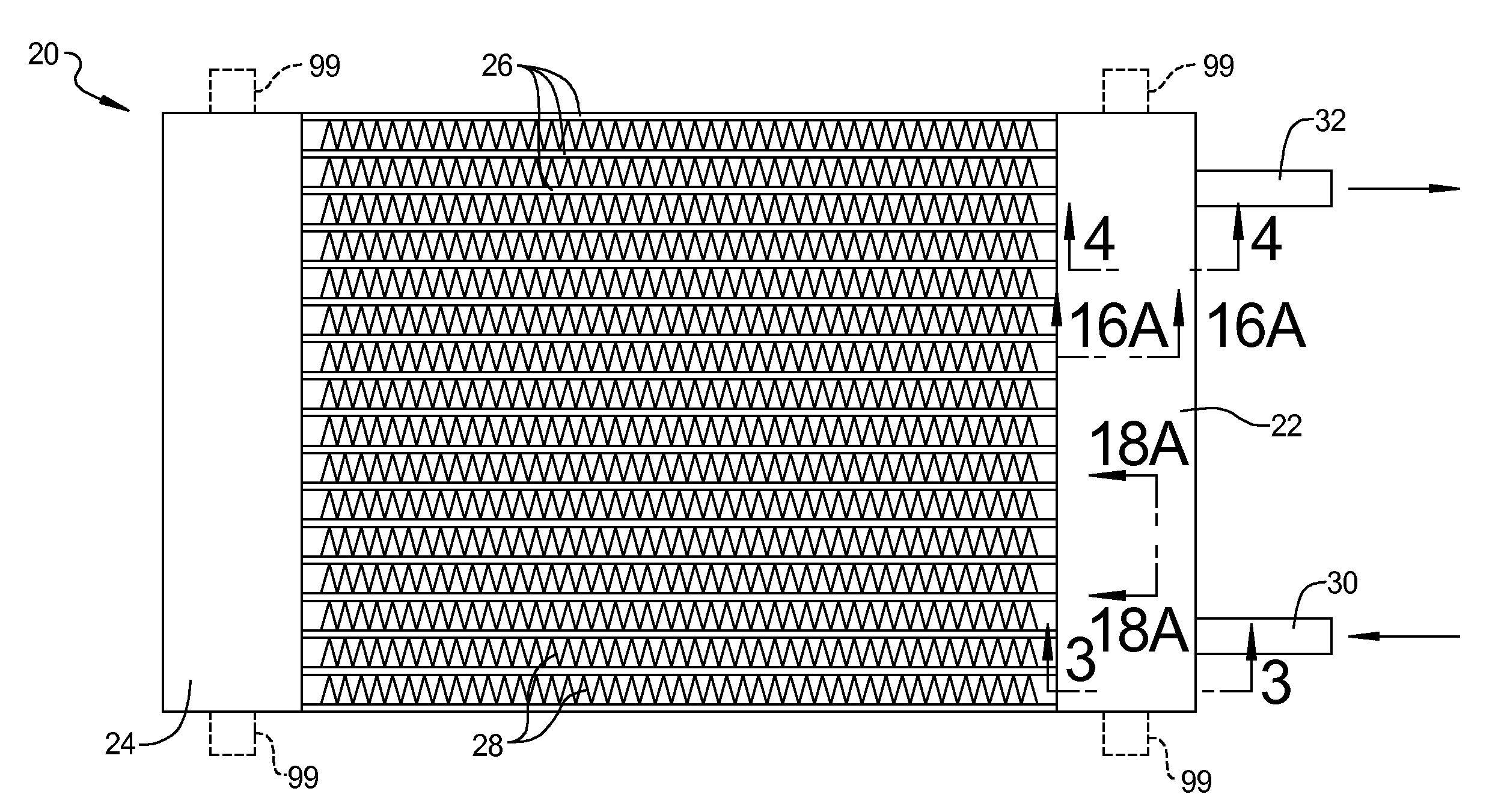
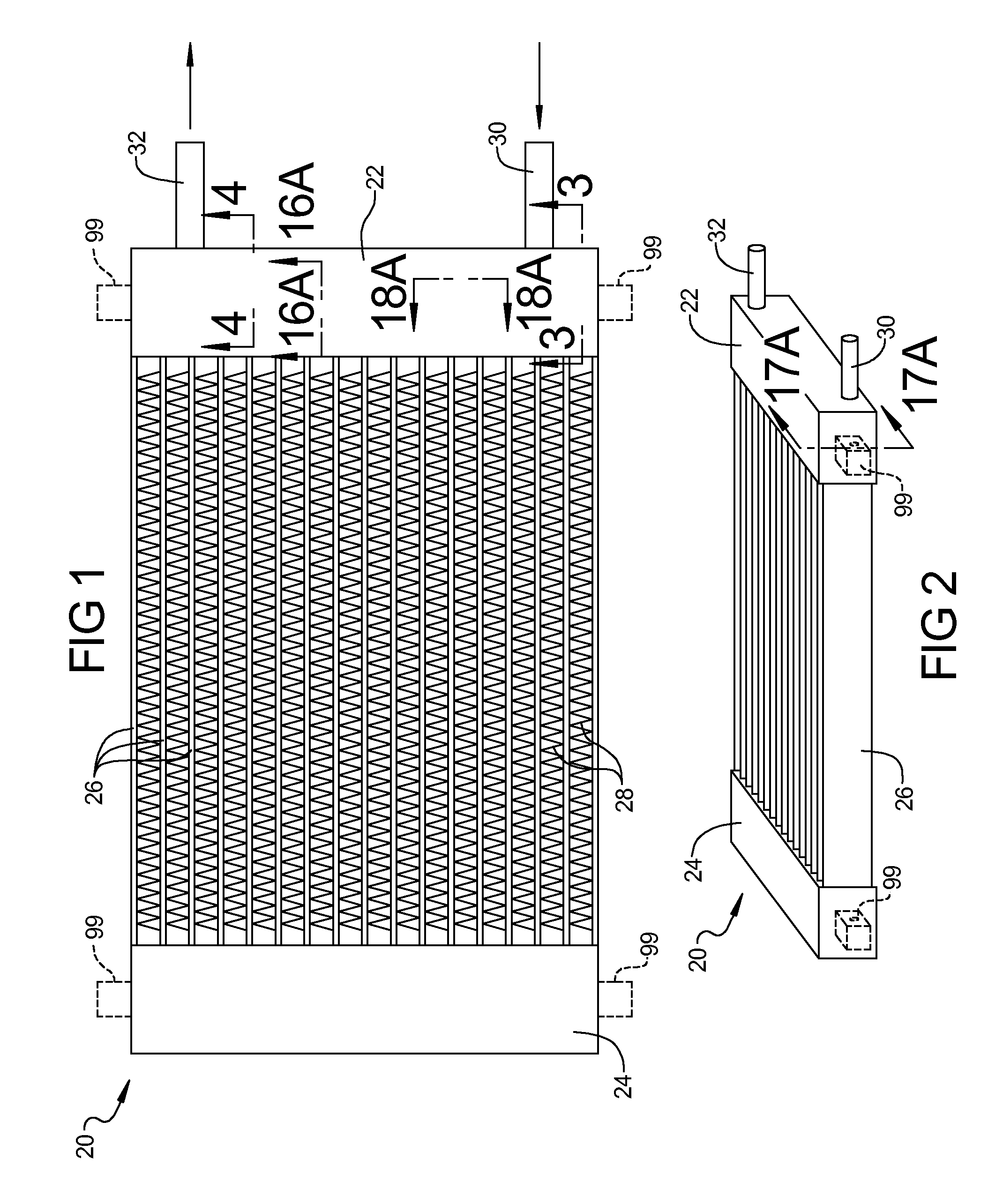
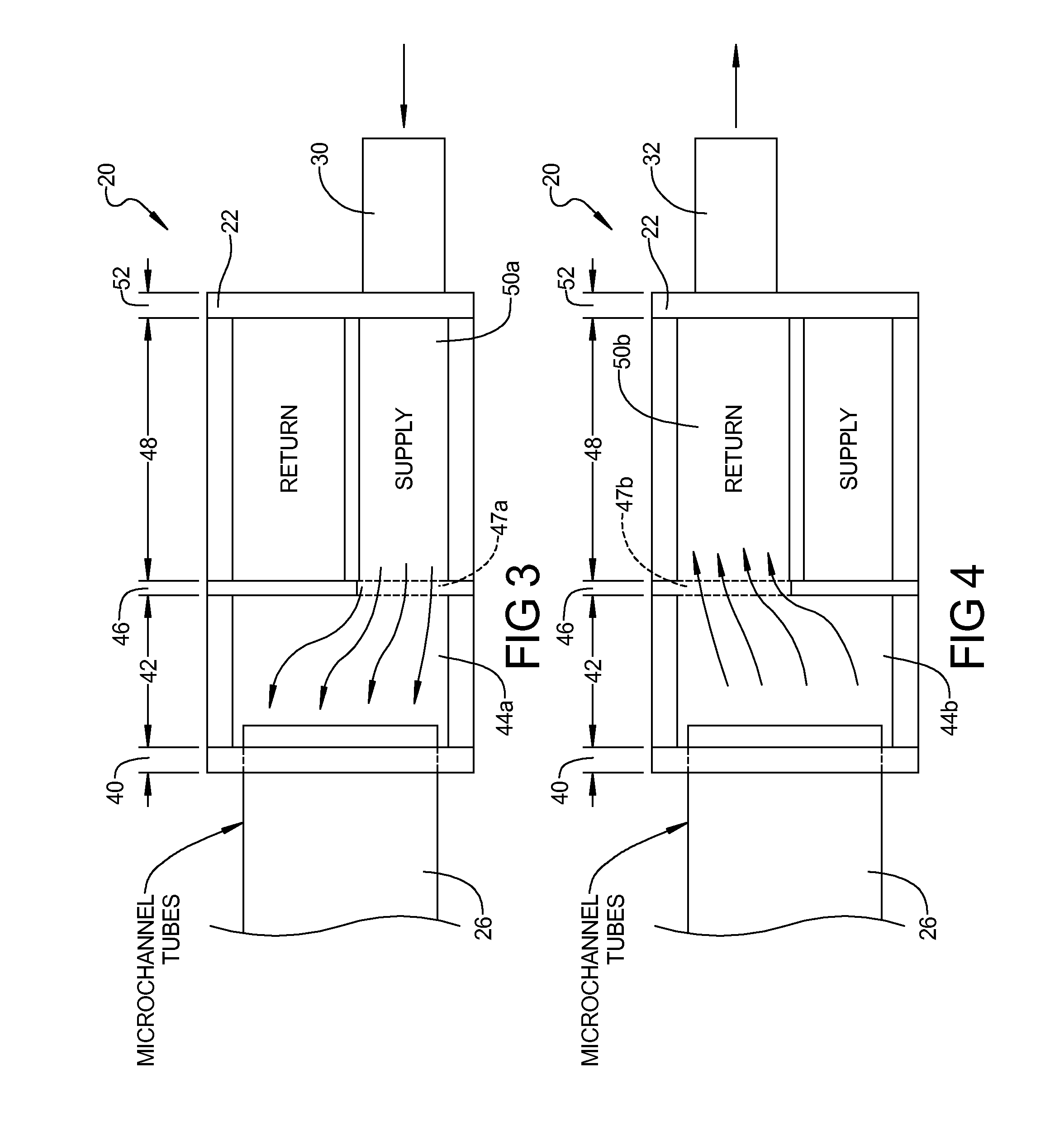
[0044]Referring to FIGS. 1 and 2, a microchannel heat exchanger 20 utilizing manifolds 22, 24 according to the present teachings is shown. Heat exchanger 20 includes a plurality of microchannel tubes 26 that extend between and communicate with manifolds 22, 24. A plurality of fins 28 is disposed between adjacent tubes 26 in heat-conducting relation therewith. A supply line 30 and a return line 32 are connected to and communicate with manifold 22. Supply line 30 is operable to supply a flow of coolant to heat ex...


PUM

PropertyMeasurementUnit
sizeaaaaaaaaaa
distanceaaaaaaaaaa
sizesaaaaaaaaaa

Abstract

A heat exchanger can have a manifold which includes a plurality of laminated sheets that allow a customization of the heat exchanger. The design can allow for a more optimal flow of coolant to areas of high load, thereby making the temperature distribution across the heat exchanger more uniform, or intentionally non-uniform. Furthermore, the laminated sheets can allow multiple circuits to be employed in the heat exchanger such that different coolants can be utilized therein and maintained separate from one another. The tubes can be microchannel tubes. A single set of manifolds can be used with multiple heat exchanger cores to provide a more compact heat exchanger. Mounting features can be integral with a group of the sheets.

Description

CROSS-REFERENCE TO RELATED APPLICATION[0001]This application claims the benefit of U.S. Provisional Application No. 61 / 030,600, filed on Feb. 22, 2008. The entire disclosure of the above application is incorporated herein by reference.FIELD[0002]The present invention relates to heat exchangers and, more particularly, to laminated sheet manifolds for microchannel heat exchangers.BACKGROUND AND SUMMARY[0003]The statements in this section merely provide background and summary information related to the present teachings and may not constitute prior art.[0004]Microchannel heat exchangers can be used to transfer heat between a fluid, such as air, flowing outside of the heat exchanger and a fluid, such as a coolant, flowing through the heat exchanger. One such application is in the use of computer / electronic equipment. As the power density of computer / electronic equipment increases, it becomes favorable to position cooling components, such as heat exchangers, as close to the heat source a...

Claims


Application Information

Patent Timeline
Patent Type & Authority Applications(United States)
IPC IPC(8): F28F9/02
CPCF28D1/0426F28D1/0476F28D1/0478F28D1/05391F28F9/0221F28F2260/02Y10T29/49389B29C67/0051F28D1/05375F28F2255/00F28D1/05383F28F2255/12H05K7/20154
Inventor SCHRADER, TIMOTHY J.SPEARING, IAN G.
Owner VERTIV CORP
Why Eureka
Try Eureka