Software enabled control for systems with luminent devices

a technology of luminescent devices and software enabled control, applied in the direction of instruments, semiconductor lasers, lasers, etc., can solve the problems of inflexible and inability to change, laborious and time-consuming process of design and characterization, adaptation or change of these controls also requires laborious redesign

Inactive Publication Date: 2004-04-08
SHEPERD VENTURES II L P AS COLLATERAL AGENT +1
View PDF3 Cites 11 Cited by
  • Summary
  • Abstract
  • Description
  • Claims
  • Application Information

AI Technical Summary

Problems solved by technology

The specific nature of these control approaches renders them inflexible and unable to change when the luminent device is changed, or with changing environmental conditions, situations in the field, or with the type of application.
Changes to address different conditions need to be carried out with a laborious and time-consuming proce

Method used


Image

  • Software enabled control for systems with luminent devices
  • Software enabled control for systems with luminent devices
  • Software enabled control for systems with luminent devices

Examples


Embodiment Construction

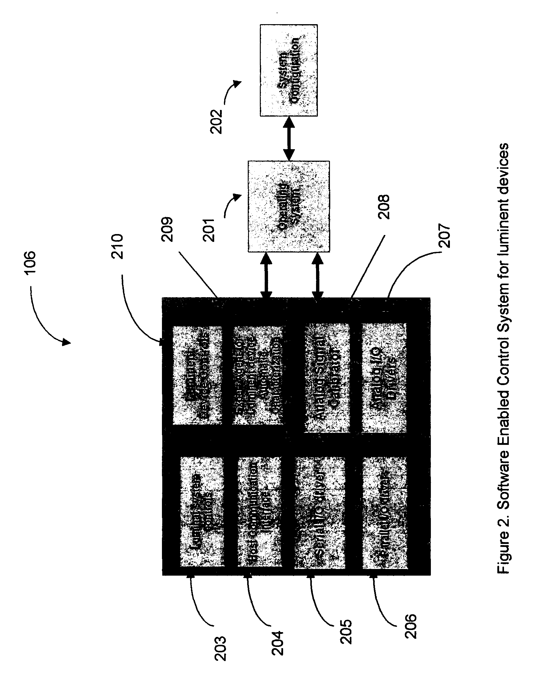
[0015] There are four elements, which are part the Software Enabled Control for Systems with Luminent Devices. These elements are:

[0016] 1. System configuration method;

[0017] 2. Software Enabled Control System is a system that is reconfigurable and uses embedded intelligence and decision-making to control hardware or mathematical objects used in a luminent system;

[0018] 3. A configuration database; and

[0019] 4. Dynamic performance optimization.

[0020] System Configuration Method

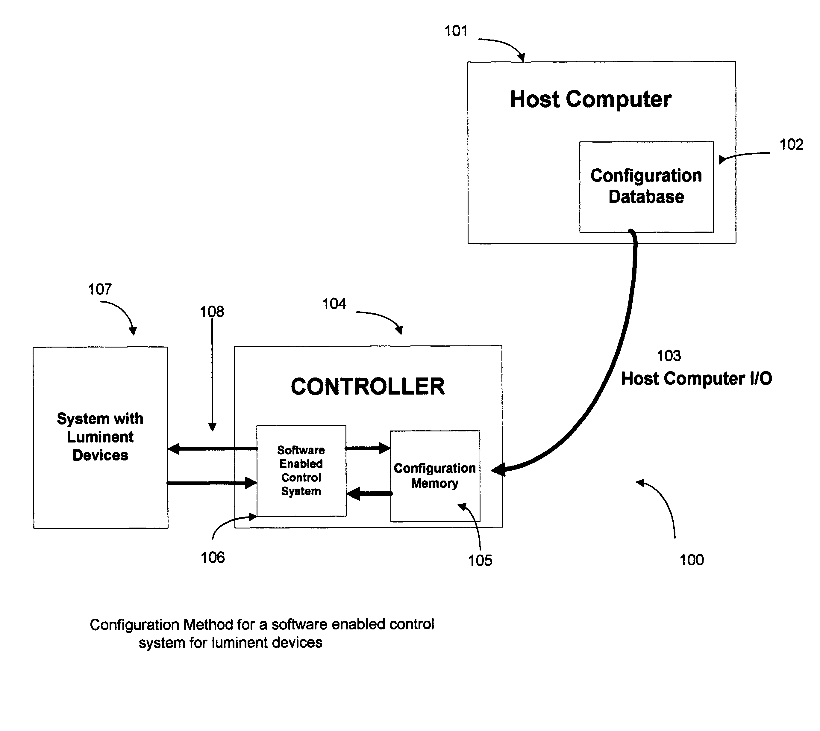
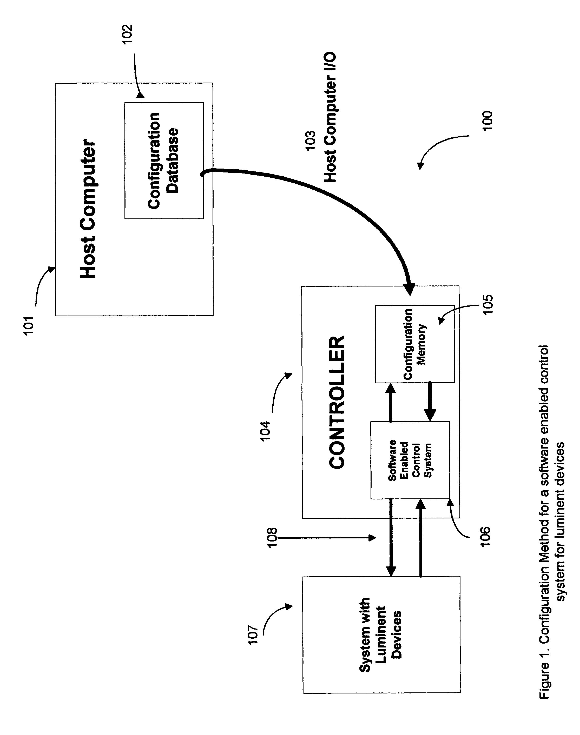
[0021] FIG. 1 illustrates a system configuration method 100 for a Software Enabled Control System 106. The method 100 consists of a Host computer 101 used for configuration of the Control System 106. The Host computer can also be part of a larger system. Some examples of larger systems are a network, a liquid crystal display unit, or system containing one or more lasers. The Host computer 101 contains a Configuration Database 102. The Configuration Database 102 contains information necessary to configure the c...


PUM


Abstract

A software enabled control method that allows dynamic configuration of the operation of a control system. The configuration can be done in a factory calibration or while the system is running in the field in communication with a Host computer. The Host computer may communicate through a serial or parallel I/O. Because the control system has an expert system with built-in mathematical models and intelligence for the system with luminent devices, once the software enabled control system has been configured and given set points for desired target performance, it will regulate performance of the system with a luminent device in a manner that does not require intervention of the Host computer. The system contains performance optimization monitors based on predetermined criteria. The results of the monitors are available to the user or a Host computer through one of the available I/Os. The present invention allows flexibility to address various luminent devices using the same software architecture and similar algorithms. The present invention has a control system that can be configured to address a specific luminent device allowing for compensation of manufacturing. The control system also has algorithms that can be dynamically changed in light of changing environmental conditions.

Description

REFERENCES[0001] This application is a continuation in part patent for pending application for the Electro-Optic System Controller and method of operation Ser. No. 09 / 724, 692. This utility patent is also filed based on Provisional Application No. 60 / 457, 095 titled Software Enabled Control System for Electro-Optic Device.[0002] 1. Field of the Invention[0003] The invention relates to methods used to control a system containing a luminent device. Possible luminent devices can be, but are not limited to, a laser, a light emitting diode, and a cold cathode fluorescent light. The invention teaches methods for control that rely on mathematical models that can be configured dynamically in order to satisfy the requirements for any luminent device. A Host processor carries out the configuration.[0004] 2. Description of the Prior Related Art[0005] Present approaches use a variety of solutions. Existing control approaches for luminent device systems are generally based on specific analog or ...

Claims


Application Information

Patent Timeline
IPC IPC(8): H01S5/068
CPCG01R1/071G01R31/002H01S5/0617H01S5/068H04B10/66H01S5/06812H01S5/06825H01S5/06832H01S5/06804
Inventor SANCHEZ OLEA, JORGE
Owner SHEPERD VENTURES II L P AS COLLATERAL AGENT
Why Eureka
Try Eureka