Charging apparatus of bicycle dynamo

a charging apparatus and bicycle technology, applied in cycle equipment, secondary cell servicing/maintenance, machines/engines, etc., can solve the problems of insufficient voltage supply, components will malfunction, and it is difficult to determine the optimum capacity of the capacitor c2

Inactive Publication Date: 2004-04-22
SHIMANO INC
View PDF2 Cites 15 Cited by
  • Summary
  • Abstract
  • Description
  • Claims
  • Application Information

AI Technical Summary

Benefits of technology

[0046] As described above, the present invention makes it possible to obtain a stable charging voltage using a circuit with a simple configuration even when using a dynamo for a bicycle that does not have a stable output voltage.

Problems solved by technology

In such a case, there is a chance that a sufficient voltage cannot be supplied to electrical components of the bicycle, such as an electrically driven transmission, and thus, there is a risk that these components will malfunction.
However, since the output frequency in the dynamo GE changes depending on the speed at which the bicycle is traveling, it is difficult to determine an optimum capacity for the capacitor C2.
In such a case, charging the capacitor C2 during the next half-cycle will require more time, and thus, charging the capacitor C2 cannot be performed efficiently.
However, when the speed at which the bicycle is traveling is low, there is a chance that the charging voltage of the second capacitor C2 may be discharged below a specified voltage during the second half-cycle.

Method used


Image

  • Charging apparatus of bicycle dynamo
  • Charging apparatus of bicycle dynamo
  • Charging apparatus of bicycle dynamo

Examples


first embodiment

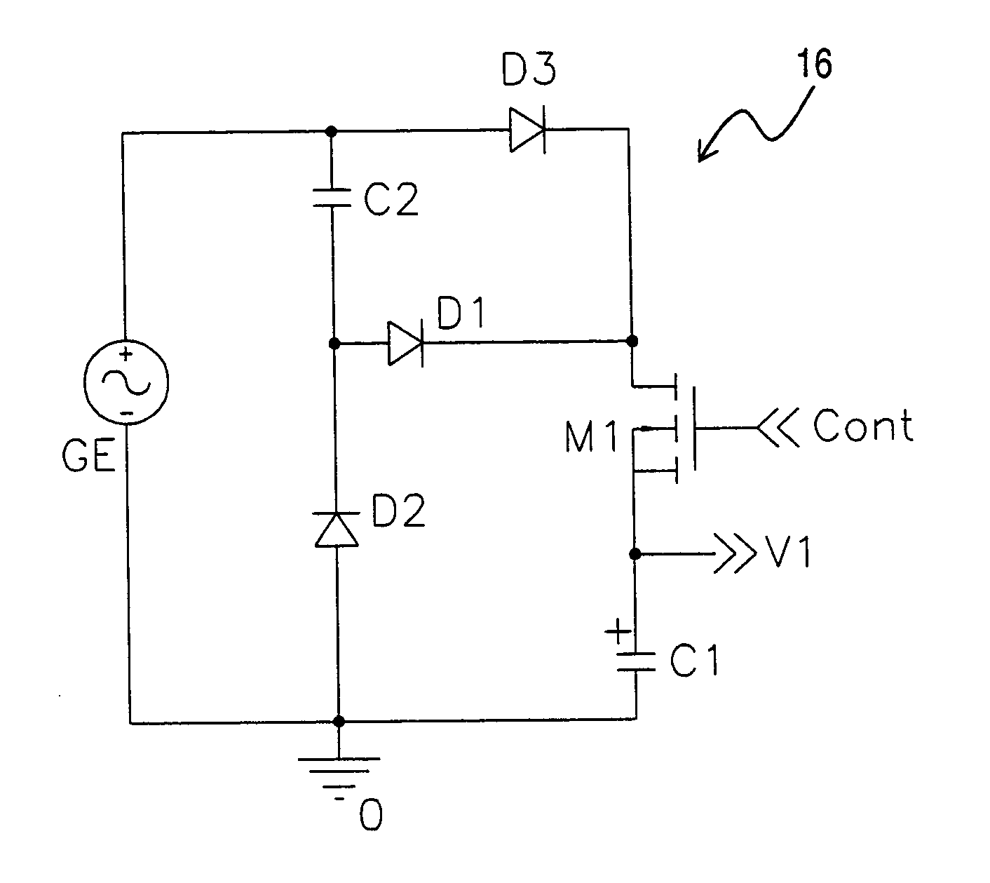
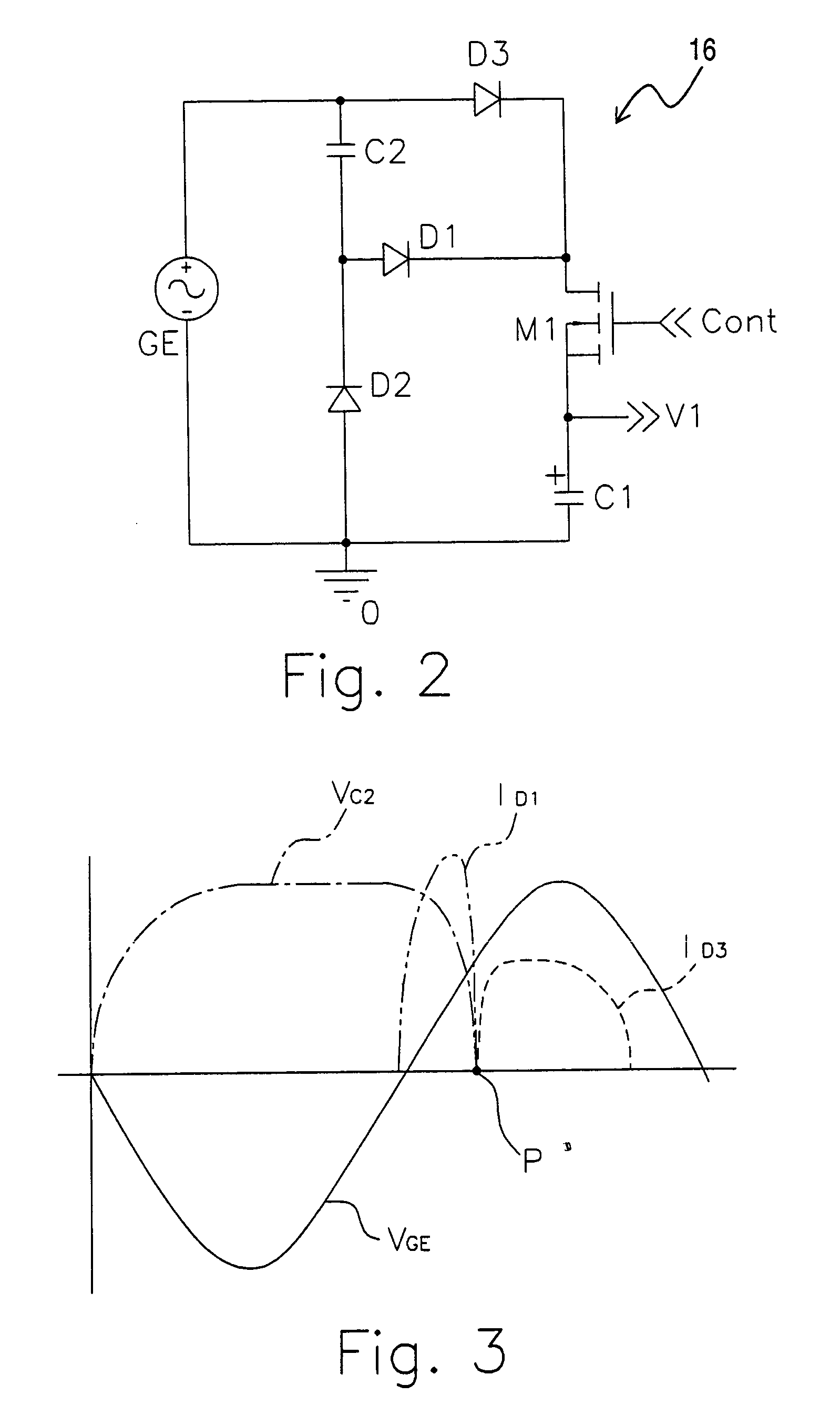
[0039] For example, in the circuit of the present invention explained above, the transistor M1 is required to be turned on in order to charge the first capacitor C1. In order to turn on the transistor M1, a control voltage is required be applied to the gate of the transistor M1. The control voltage is required to be equal to or higher than the sum of voltage V.sub.C1 at both ends of the first capacitor C1 and the voltage required to turn on the transistor M1. However, when the voltage charged in the first capacitor C1 is not sufficient, a sufficient control voltage cannot be applied to the gate of the transistor M1, and thus, it is necessary to provide a separate power supply, such as a battery.

second embodiment

[0040] In the present invention, the control voltage applied to the gate of the transistor M1 is produced by providing the half-wave voltage doubler circuit for switching, as seen in FIG. 4. More specifically, the half-wave voltage doubler circuit for switching basically comprises a fourth capacitor C4 (switching charging element), a third capacitor C3 (switching half-wave charging element), a pair of (fourth and fifth) diodes D4 and D5, and a pair of-resistors R1 and R2. One end of the third capacitor C3 is connected to the dynamo GE and the other end is connected to the cathode of the fourth diode D4. The anode of the fourth diode D4 is connected to the dynamo GE. The fifth diode D5 is connected in the forward direction between the third capacitor C3 and the fourth capacitor C4. The resistor R2 is connected in series to the fifth diode D5. The resistor R1 is connected between the fourth capacitor C4 and the transistor M1.

[0041] Thus, in the charging apparatus 116 of the second emb...


PUM

PropertyMeasurementUnit
voltageaaaaaaaaaa
electric potentialaaaaaaaaaa
electrical energyaaaaaaaaaa

Abstract

A charging apparatus of a bicycle dynamo is configured and arranged to charges a voltage generated by a dynamo GE and comprises a first capacitor C1, a second capacitor C2, a first diode D1 and a third diode D3. The second capacitor C2 is supplied and charged by the dynamo output during the negative half-cycle of the dynamo output. During the positive half-cycle of the dynamo output the first diode D1 supplies the electrical charge that was charged in the second capacitor C2 to the first capacitor C1. During the positive half-cycle of the dynamo output the third diode D3 supplies the dynamo output to the first capacitor C1 when the charging voltage of the second capacitor C2 is equal to or less than a specified voltage.

Description

[0001] 1. Field of the Invention[0002] The present invention relates to a charging apparatus of a bicycle dynamo. In particular, the present invention relates to a charging apparatus that is charged by a voltage generated by a bicycle dynamo to allow efficient and stable charging when a dynamo output changes without a steady travel speed.[0003] 2. Background Information[0004] In recent years, some bicycles are equipped with an automatic transmission. An electrically-driven transmission has been used as the automatic transmission of the bicycles. These types of bicycle are usually equipped with a dynamo for driving the electrically-driven transmission as well as a charging system for charging a storage device from a voltage generated by the dynamo. Because the voltage generated by the dynamo is an alternating current voltage, half-wave rectification or full-wave rectification is performed in the charging system.[0005] However, a voltage generated from the dynamo for bicycle fluctuate...

Claims


Application Information

Patent Timeline
Patent Type & Authority Applications(United States)
IPC IPC(8): B60K1/02B62J99/00B60R16/02H01M10/44H02J7/00H02J7/14
CPCH02J7/1407
Inventor UNO, KOUJI
Owner SHIMANO INC
Why Eureka
Try Eureka