
Liquid crystal display device and electronic apparatus

Active Publication Date: 2004-04-22
138 EAST LCD ADVANCEMENTS LTD
View PDF4 Cites 16 Cited by
  • Summary
  • Abstract
  • Description
  • Claims
  • Application Information

AI Technical Summary

Benefits of technology

[0008] Further, another object of the present invention is to provide an electronic apparatus, which is capable of high quality display, comprising the above liquid crystal display device.
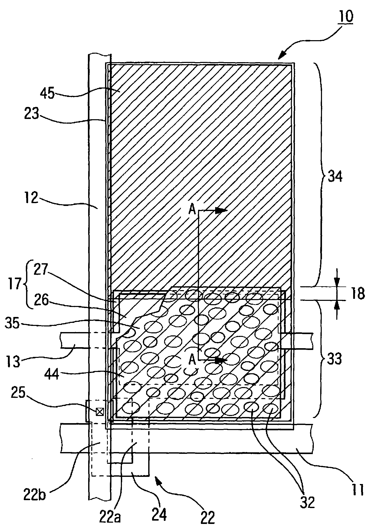
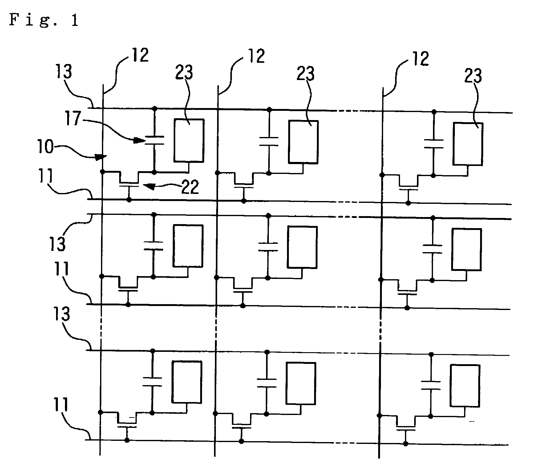
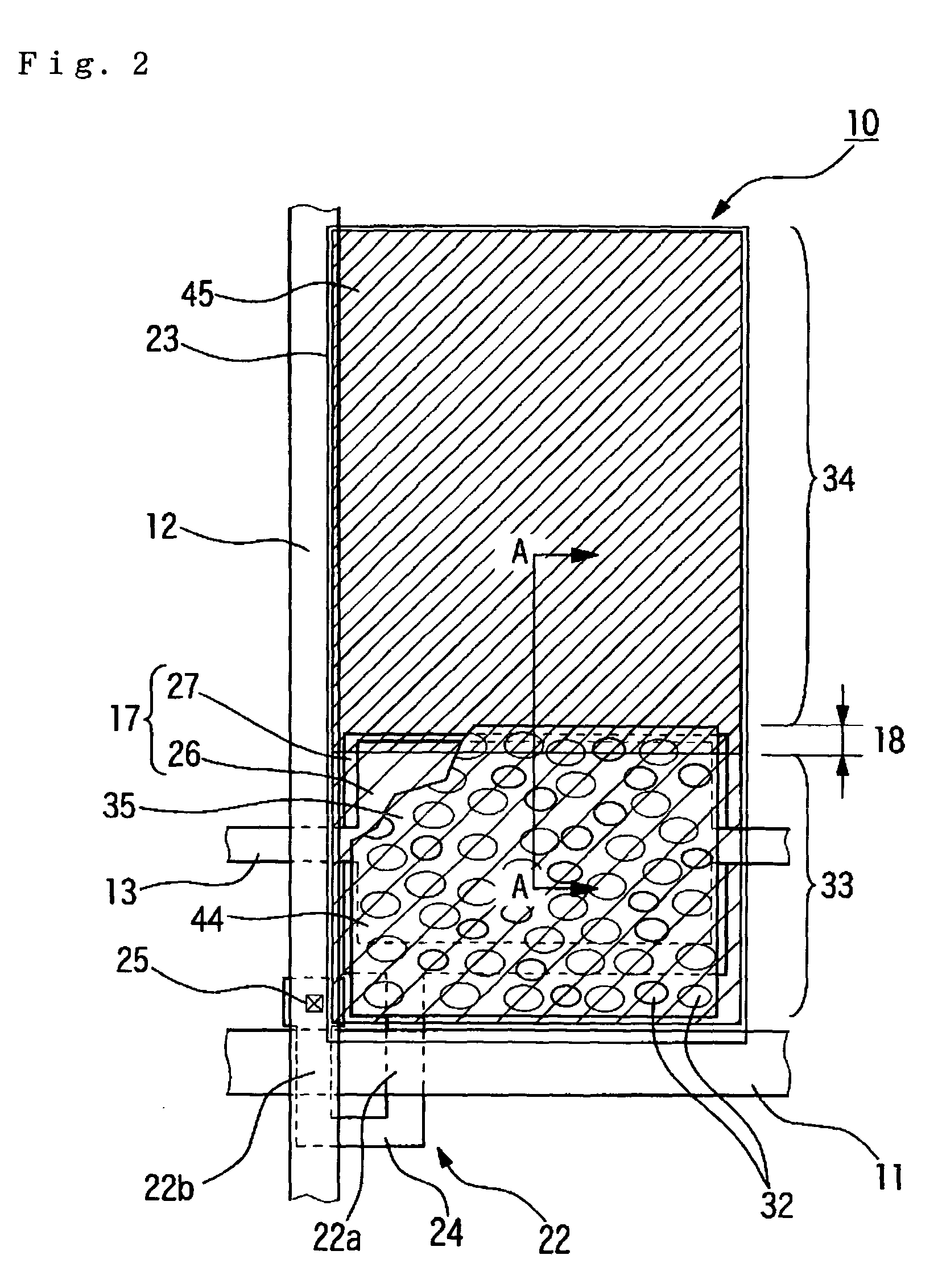
[0010] In the liquid crystal display device according to the present invention, the inclined region, which is an inferior display portion, is disposed in a plane region of the reflection layer, and the second color material whose degree of coloration is comparatively high extends to the inclined region. That is, light incident on the inclined region is transmitted through the second color material layer having a high degree of coloration, is reflected on the reflection layer, and thereafter, is again transmitted through the second color material layer having a high degree of coloration to reach observers. Therefore, the luminance reduces remarkably. In the inclined region between the reflective display region and the transmissive display region whose thickness of the liquid crystal layer is different from each other, because the thickness of the liquid crystal layer varies consecutively, alignment of the liquid crystal becomes irregular. Therefore, it is impossible to prevent the leakage light from occurring. However, by the above structure, observers hardly recognize the leakage light of the inclined region. Further, it is possible to prevent a contrast of the reflective display from being lowered. Since the leakage light of the inclined region does not affect the contrast in the transmissive display, a high contrast display can be obtained. In addition, in the liquid crystal display device according to this invention, it does not need to provide a light shielding film in the inclined region. Thus, there is an advantage that a high luminance display can be obtained in comparison to structures having such light shielding film.
[0011] Next, the liquid crystal display device according to this invention may have a structure that the first color material layer and the second color material layer are formed directly on the reflection layer. According to the above structure, it is possible to effectively prevent a color drift in the reflective display.
[0012] Next, the liquid crystal display device according to this invention may have a structure that the first color material layer and the second color material layer partially overlap each other in the inclined region. According to the above structure, in the portion where the first color material layer and the second color material layer partially overlap each other, the chromaticity of the color material layer becomes much higher and transmittance thereof lowers. Therefore, by disposing the overlapping portion in the inclined region, it is possible to reduce the leakage light from the inclined region and to increase the display contrast than the structures mentioned above.
[0014] If the second color material layer is disposed on the reflection layer, a display luminance reduces a great deal in the region as same as the aforementioned structure. Therefore, it is possible to maximize the luminance in the reflective display by not disposing the color material layer in the reflective display region according to the above structure.
[0015] An electronic apparatus according to the present invention can include any one of the aforementioned liquid crystal display devices according to the present invention in a display unit thereof. According to such a structure, this invention can provide an electronic apparatus capable of switching between the transmissive display and the reflective display, capable of performing a bright, high-contrast display in both the transmissive display and the reflective display, and capable of performing a bright, high-contrast display even around a boundary of the regions used in the transmissive display and the reflective display.

Problems solved by technology

Therefore, the thickness of the liquid crystal layer varies consecutively in the boundary portion of the transmissive display region and the reflective display region so that the retardation An-d also varies consecutively and turns out to be unsuitable for both transmissive display light and reflective display light in this portion.
But the fact is that light leakage occurs in the boundary portion of the transmissive display region and the reflective display region, and there is a problem that the contrast is lowered.
Therefore, it is impossible to prevent the leakage light from occurring.
However, by the above structure, observers hardly recognize the leakage light of the inclined region.
Furthermore, no light shielding layer for covering the inclined region is provided in either of the liquid crystal display devices.

Method used


Image

  • Liquid crystal display device and electronic apparatus
  • Liquid crystal display device and electronic apparatus
  • Liquid crystal display device and electronic apparatus

Examples


Embodiment Construction

% 30:1 100:1 Comparative 30% 21:1 100:1 example

[0057] While this invention has been described in conjunction with specific embodiments thereof, it is evident that many alternatives, modifications, and variations will be apparent to those skilled in the art. Accordingly, preferred embodiments of the invention as set forth herein are intended to be illustrative, not limiting. Various changes may be made without departing from the spirit and scope of the invention.


PUM


Abstract

The invention provides a transflective liquid crystal display device capable of obtaining a high contrast display in a transmissive display and a reflective display. In particular, in a liquid crystal display device according to the invention, a reflective display region and a transmissive display region can be formed in one pixel region, a reflection layer is provided on an array substrate in the reflective display region, an inclined region, in which the thickness of a liquid crystal layer varies consecutively between the transmissive display region and the reflective display region, is provided between the transmissive display region and the reflective display region, an edge of the inclined region at the transmissive display region side being formed in a plane region of the reflection layer, a first color material layer is formed in the reflective display region, and a second color material layer is formed in the inclined region and the transmissive display region, the degree of coloration of the second color material layer being higher than that of the first color material layer. The first color material layer and the second color material layer may overlap each other in the plane region of the inclined region.

Description

[0001] 1. Field of Invention[0002] The present invention relates to a transflective color liquid crystal display device.[0003] 2. Description of Related Art[0004] A transflective liquid crystal device having a structure that the thickness of a liquid crystal layer is thinner in a reflective display region than in a transmissive display region is disclosed in Japanese Unexamined Patent Application Publication No. 11-242226. Such a structure is called a multi-gap-type of structure and can be realized, for example, by providing a liquid crystal layer-thickness adjusting layer below a transparent electrode and above a reflection film of a lower substrate. In the liquid crystal layer-thickness adjusting layer, a portion corresponding to the transmissive display region becomes an opening portion. Namely, in the transmissive display region, the thickness of the liquid crystal layer is thicker than that of the reflective display region by the thickness of the liquid crystal layer-thickness ...

Claims


Application Information

Patent Timeline
IPC IPC(8): G02F1/1335G02F1/1333
CPCG02F1/133371G02F1/133555G02F1/133514G02F1/1335
Inventor ITOH, TOMOYUKIMURAI, ICHIRO
Owner 138 EAST LCD ADVANCEMENTS LTD
Learn More