
Iron base rare earth alloy powder and compound comprising iron base rare earth alloy powder and permanent magnet using the same

a rare earth alloy and powder technology, applied in the direction of magnetism of inorganic materials, magnetic materials, magnetic bodies, etc., can solve the problems of poor flowability or packability of the compound obtained by mixing the conventional rapidly solidified magnet powder with the resin (or rubber) powder during the compaction process, and the material with poor flowability. to achieve the effect of improving the flowability

Inactive Publication Date: 2004-04-29
SUMITOMO SPECIAL METAL CO LTD
View PDF6 Cites 38 Cited by
  • Summary
  • Abstract
  • Description
  • Claims
  • Application Information

AI Technical Summary

Benefits of technology

[0012] In order to overcome the problems described above, a primary object of the present invention is to provide a compound of which the flowability is improved by controlling the particle size distribution of an iron-based rare-earth alloy powder for use to make a bonded magnet, and provide such an iron-based rare-earth alloy powder.

Problems solved by technology

Accordingly, a compound obtained by mixing the conventional rapidly solidified magnet powder with a resin (or rubber) powder exhibits poor flowability or packability during the compaction process thereof.
In that case, however, the magnet powder percentage is limited.
Or only limited compaction methods and / or compact shapes are available to compact such a material with poor flowability.
However, it is difficult to make a magnet powder exhibiting sufficient magnetic properties by a gas atomization process.
Thus, this method is far from being an industrially applicable method.
Thus, it is hard to obtain fine particles.
Consequently, according to the method disclosed in the publication identified above, the yield of those fine particles having sufficient magnetic properties is very low and the productivity is also very bad because a classification process step must be carried out to obtain particles with a desired particle size.

Method used


Image

  • Iron base rare earth alloy powder and compound comprising iron base rare earth alloy powder and permanent magnet using the same
  • Iron base rare earth alloy powder and compound comprising iron base rare earth alloy powder and permanent magnet using the same
  • Iron base rare earth alloy powder and compound comprising iron base rare earth alloy powder and permanent magnet using the same

Examples


example 2

[0184] In a second specific example of the present invention to be described below, a bonded magnet was formed by an injection molding process.

[0185] First, the first iron-based rare-earth alloy powder (with no Ti) was prepared in the following manner.

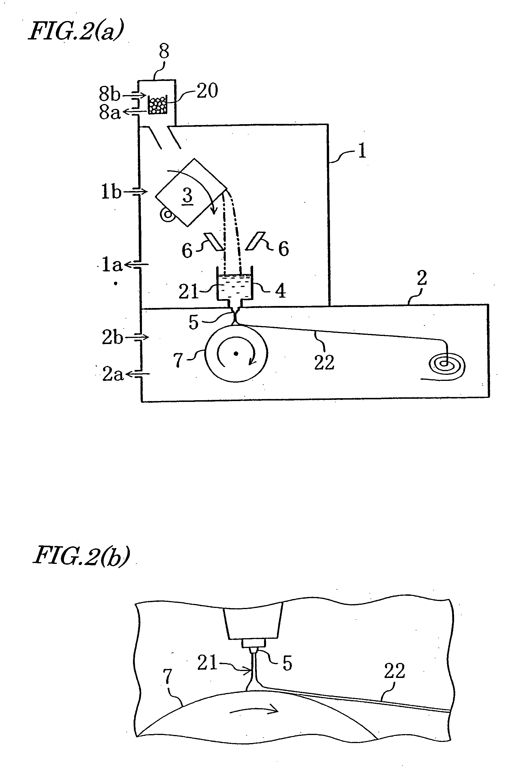
[0186] A material alloy, obtained by mixing respective materials so as to have an alloy composition Nd.sub.4.5Fe.sub.73.0B.sub.18.5Co.sub.2Cr.sub.2-, was melted by a high frequency heating process. Then, the resultant molten alloy was teemed at a feeding rate of 5 kg / min onto the surface of a copper roller, which was rotating at a roller surface peripheral velocity of 8 m / s, by way of a shoot. In this manner, a rapidly solidified alloy thin strip with a thickness of 120 .mu.m was obtained. This rapidly solidified alloy had a structure in which Fe.sub.23B.sub.6 and amorphous phases coexisted.

[0187] Next, the resultant rapidly solidified alloy was coarsely pulverized to 1 mm or less, which was then thermally treated at 700.degree. C. for...

example 3

[0197] In this specific example, the best mixing ratio of the first and second rare-earth alloy powders was looked for to increase the mass-productivity of bonded magnets.

[0198] A nanocomposite magnet powder having the same composition as the second specific example described above was used as the first iron-based rare-earth alloy powder. However, since some variations in magnetic properties were naturally expected from mass-produced ones, the nanocomposite magnet powder used had relatively low magnetic properties including B.sub.r of 0.92 T, H.sub.cJ of 370 kA / m and (BH).sub.max of 73 kJ / m.sup.3. This magnet powder had particle sizes of 53 .mu.m or less, a mean particle size of 38 .mu.m or less, and an aspect ratio of 0.88.

[0199] Also, MQP 15-7 was used as the second iron-based rare-earth alloy powder. In the second example described above, the particle size distribution was adjusted to a mean particle size of 100 .mu.m by classifying the MQP 15-7 powder. In this specific example o...

example 4

[0206] A material, which had been mixed to have an alloy composition including 9 at % of Nd, 11 at % of B, 3 at % of Ti, 2 at % of Co and Fe as the balance and a weight of about 5 kg, was introduced into a crucible and then inductively heated by a high frequency heating technique within an Ar atmosphere having a pressure maintained at 50 kPa, thereby obtaining a molten alloy.

[0207] The crucible was tilted to directly feed the molten alloy onto a pure copper chill roller, having a diameter of 250 mm and rotating at a roller surface peripheral velocity of 15 m / s, by way of a shoot, thereby rapidly cooling and solidifying the molten alloy. In feeding the melt onto the roller, the melt feeding rate was controlled to 3 kg / mm by adjusting the tilt angle of the crucible.

[0208] As for the rapidly solidified alloys obtained in this manner, the thicknesses of 100 flakes were measured with a micro meter. As a result, the rapidly solidified alloys had an average thickness of 70 .mu.m with a sta...


PUM

PropertyMeasurementUnit
Grain sizeaaaaaaaaaa

Abstract

An iron-based rare-earth alloy powder includes: a first iron-based rare-earth alloy powder, which has a mean particle size of 10 mum to 70 mum and of which the powder particles have aspect ratios of 0.4 to 1.0; and a second iron-based rare-earth alloy powder, which has a mean particle size of 70 mum to 300 mum and of which the powder particles have aspect ratios of less than 0.3. The first and second iron-based rare-earth alloy powders are mixed at a volume ratio of 1:49 to 4:1. In this manner, an iron-based rare-earth alloy powder with increased flowability and a compound to make a magnet are provided.

Description

[0001] The present invention relates to an iron-based rare-earth alloy powder, which can be used effectively as a material for a bonded magnet, and a method of making the alloy powder. The present invention also relates to a bonded magnet made from the rare-earth alloy powder and further relates to various types of electric equipment including the bonded magnet.[0002] A bonded magnet is currently used in various types of electric equipment including motors, actuators, loudspeakers, meters and focus convergence rings. A bonded magnet is a magnet obtained by mixing together a magnet powder and a binder (such as a rubber or a resin) and then compacting and setting the mixture.[0003] An iron-based rare-earth alloy (e.g., Fe--R--B based, in particular) nanocomposite magnet has recently been used more and more often as a magnet powder for a bonded magnet because such a magnet powder is relatively cost effective. The Fe--R--B based nanocomposite magnet is an iron-based alloy permanent magn...

Claims


Application Information

Patent Timeline
IPC IPC(8): B22F3/00B22F3/02B22F1/00B22F3/22B22F7/08C22C1/04C22C33/02C22C38/00H01F1/053H01F1/057H01F1/058H01F1/06H01F1/08
CPCB22F3/225B22F7/08H01F1/058H01F1/0578H01F1/0571C22C33/0207C22C1/0441B22F2999/00B22F2998/10B22F2998/00B22F9/008B22F9/04B22F1/0003B22F3/22B22F1/08B22F1/09H01F1/053
Inventor KANEKIYO, HIROKAZUKITAYAMA, HIROKAZUHIROSAWA, SATOSHIMIYOSHI, TOSHIO
Owner SUMITOMO SPECIAL METAL CO LTD
Learn More