Method of manufacturing a device, device, and electronic apparatus

Active Publication Date: 2004-04-29
SEIKO EPSON CORP
View PDF4 Cites 15 Cited by
  • Summary
  • Abstract
  • Description
  • Claims
  • Application Information

AI Technical Summary

Problems solved by technology

These methods invite deterioration of the workability and increase of the manufacturing cost, since various processes such as a film formation process, a photolithographic process, a development process, and the like are required.
However, the picture element pitch (the pattern pitch) of the color filter and the nozzle interval "a" of the liquid drop discharge head will not necessarily agree with one another.
Due to this problems occur as described previously, and things such as scanning while tilting the head have been performed, and due to this it has not been possible to perform discharge of a pattern at good efficency, even when using a head equipped with a plurality of nozzles.
However, problems arise with the above described background technique, as will be described below.
Although with the above described publicly disclosed technique it is possible to make the pattern pitch by in the non-scanning direction and the nozzle pitch in the non-scanning direction agree with one another, there are problems with making pattern pitch b.sub.x in the scanning

Method used


Image

  • Method of manufacturing a device, device, and electronic apparatus
  • Method of manufacturing a device, device, and electronic apparatus
  • Method of manufacturing a device, device, and electronic apparatus

Examples


Embodiment Construction

[0052] In the following, the method of manufacturing a device according to the present invention will be explained with reference to the drawings.

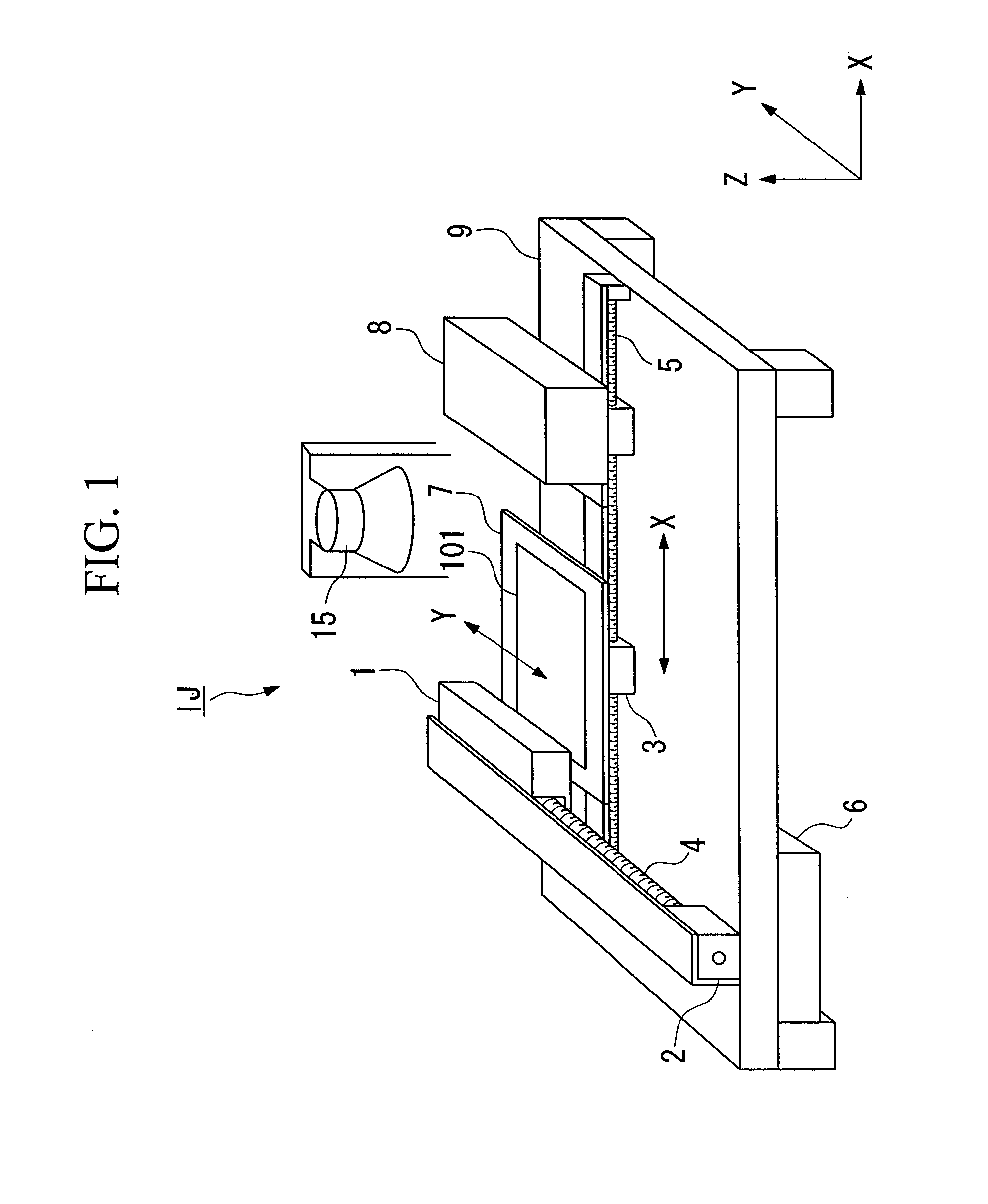
[0053] FIG. 1 is a schematic external perspective view of a liquid drop discharge device which is comprised in a liquid drop discharge head which is used in the method of manufacturing a device according to the present invention.

[0054] Referring to FIG. 1, the liquid drop discharge device IJ comprises a liquid drop discharge head 1, an X-axis direction drive shaft 4, a Y-axis direction guide shaft 5, a control device 6, a stage 7, a cleaning mechanism 8, a base 9, and a heater 15.

[0055] The stage 7 is an element for supporting a substrate 101 upon which a material in liquid form is to be provided by this liquid drop discharge device IJ, and it is provided with a fixing mechanism not shown in the figures which fixes the substrate 101 in a standard position.

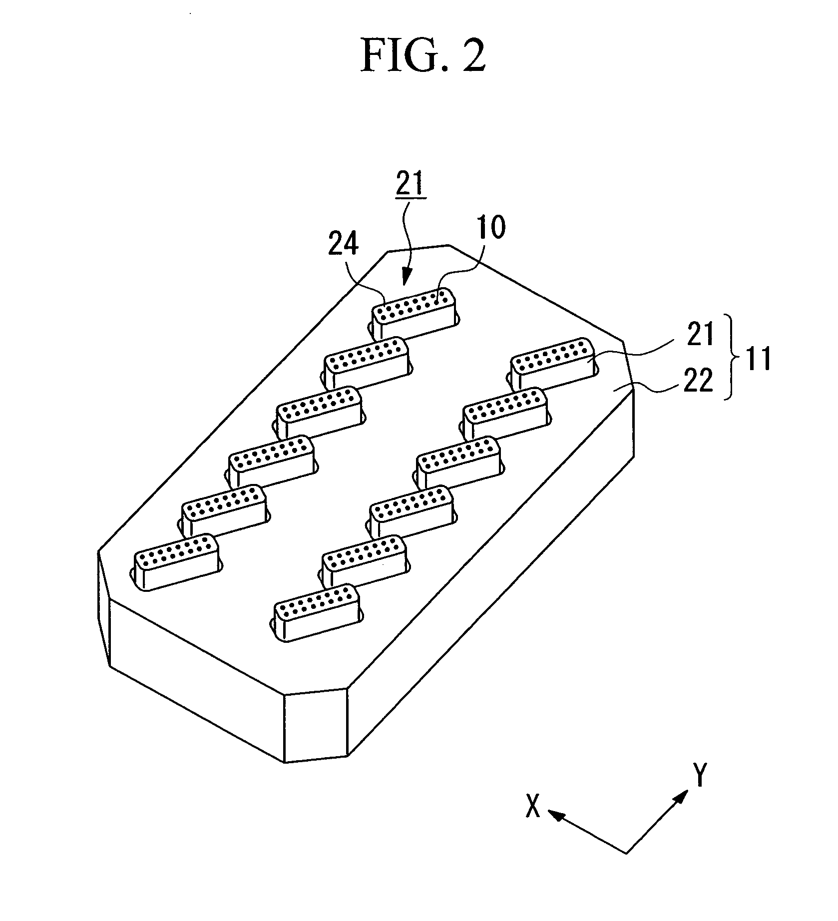
[0056] The liquid drop discharge head 1 is a liquid drop discharge head of a multi no...


PUM

PropertyMeasurementUnit
Fractionaaaaaaaaaa
Diameteraaaaaaaaaa
Sizeaaaaaaaaaa

Abstract

In this method of manufacturing a device, when discharging the liquid drops upon the substrate, a bit map made up from a plurality of pixels against which liquid drops are discharged is established upon the substrate. When establishing the pixels, when the interval of the discharge nozzles of the liquid drop discharge head 1 is taken as "a", and the size in the Y axis direction of the pixels is taken as by, the pixels are established so that the condition by=a/n is satisfied, where n is a positive integer.

Description

[0001] 1. Field of the Invention[0002] The present invention relates to a method of manufacturing a device, in which the device is manufactured by discharging material in liquid form against a substrate from a liquid drop discharge head.[0003] 2. Background Art[0004] In the past, a color filter has been used for a liquid crystal display device. The color filter is made as one unit with the liquid crystal display device, and is endowed with the functions of enhancing the picture quality and of imparting to each picture element a hue of a respective primary color. As methods for manufacturing this type of color filter, there are known a method (a dyeing method) of forming a pattern by hardening illuminated portions by illuminating light via a photo-mask onto a painted on layer of photosensitive resin, and thereafter removing the portions of the painted on layer which have not been irradiated by light so as to perform a development process, and then dyeing it; or a photolithographic me...

Claims


Application Information

Patent Timeline
IPC IPC(8): B05C5/00B05C11/10G02B5/20B05D1/26C03C17/00G02F1/13H01L27/32H01L51/00H01L51/40H01L51/56
CPCC03C17/001H01L27/3244Y10T428/12604H01L51/56H01L51/0005H10K71/135H10K59/12H10K71/00E01C15/00E01C11/225E01C5/22E01C2201/20
Inventor FURUSAWA, MASAHIROHIRAI, TOSHIMITSU
Owner SEIKO EPSON CORP
Why Eureka
Try Eureka