Ultrasound endoscope

a technology of ultrasound endoscope and endoscope, which is applied in the field of ultrasound endoscope, can solve the problems of virtually impossible to carry out maintenance and service on the ultrasound transducer, the most expensive ultrasonic transducer, and the difficult repair of the ultrasonic transducer

Inactive Publication Date: 2004-04-29
FUJI PHOTO OPTICAL CO LTD
View PDF14 Cites 70 Cited by
  • Summary
  • Abstract
  • Description
  • Claims
  • Application Information

AI Technical Summary

Problems solved by technology

Generally, in the case of an ultrasound endoscope with an electronic scan type ultrasound transducer, it is the ultrasound transducer which is most expensive among the various component part which make up the ultrasound endoscope.
Nevertheless, it has been extremely difficult to repair the ultrasound transducer when it is damaged or in the event of malfunctioning.
That is to say, it has been virtually impossible to carry out maintenance and service on the ultrasound transducer.
Therefore, when the rigid tip end section is detached from the angle section, the jobs of maintenance and service have been limited to the solid-state image sensor device and its wiring, the light guide and the biopsy channel tube.
Above all, internal surfaces of the biopsy channel tube are susceptible to damages since the biopsy channel is often used for insertion of puncture instruments with a sharp-pointed puncture needle.
Further, breakage could occur to the signal lines from the solid-state image sensor device.
Therefore, when the rigid tip end section is detached and pulled away from the angle section to repair or replace a certain component part, difficulties are often encountered in separating the repairing or replacing component part from other component parts which are densely packed in the rigid tip end section of the insertion instrument.
Therefore, it has been extremely difficult and troublesome to inspect, repair or replace a particular component part separately from other densely packed component parts, without damaging other component parts.
Especially, in case the ultrasound transducer and the wiring to the transducer are made detachable or separable from the rigid tip end section to facilitate maintenance and service jobs on component parts other than the ultrasound transducer and its wiring, the construction of the rigid tip end section will become too complicate and will become a great obstacle to the maintenance and service.
On such an occasion, there are increased possibilities of damaging other component parts which happen to be in the close proximity.
However, the interlocking engagement of joining wall portions may not be effective for restricting backward movements of the separable head block relative to the main casing.
Interior surfaces of a biopsy channel tube which constitutes a major part of a biopsy channel within the insertion instrument are susceptible to damages because the biopsy channel is often used for introduction of sharp-pointed instruments like a puncture needle.

Method used


Image

  • Ultrasound endoscope
  • Ultrasound endoscope
  • Ultrasound endoscope

Examples


Embodiment Construction

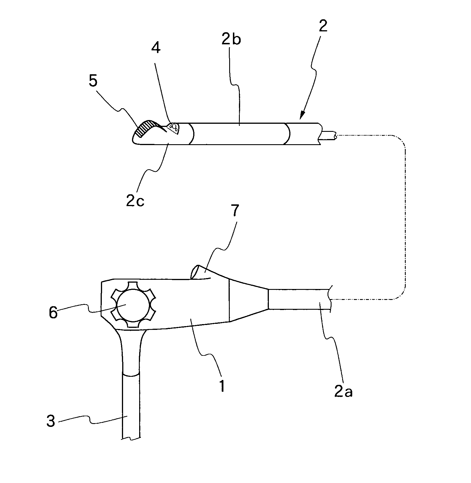
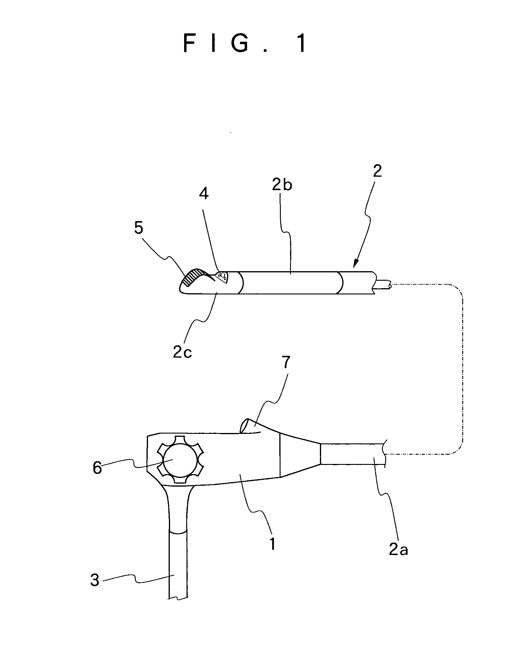
[0036] Hereafter, the present invention is described more particularly by way of its preferred embodiments with reference to the accompanying drawings. Referring first to FIG. 1, there is schematically shown general layout of a typical ultrasound endoscope. In this figure, indicated at 1 is a manipulating head assembly to be gripped by an operator, at 2 an insertion instrument to be introduced into a body cavity of a patient, and at 3 a universal cable. From proximal to fore end, the insertion instrument 2 is composed of an elongated flexible body section 2a, an angle section 2b and a rigid tip end section 2c. The flexible body section 2a has a flexible body structure which is bendable in arbitrary directions along a path of insertion toward a patient's body cavity. The rigid tip end section 2c has a rigid structure to support thereon an endoscopic observation means 4 along with an ultrasound examination means 5. The angle section 2b is provided between the flexible body section 2a ...


PUM


Abstract

A rigid tip end section which is connected to an angle section at the fore distal end of an insertion instrument of an ultrasound endoscope is housed in a casing which can be split into a main casing and a separable head block to facilitate maintenance and service of internal component parts of the rigid tip end section. An ultrasound transducer is accommodated in a front side portion of the main casing, while endoscopic observation means including an illumination means and an optical image pickup means are fitted in an inclined wall rising obliquely upward on the rear side of the ultrasound transducer. An outlet opening of a biopsy channel outlet passage is located between the ultrasound transducer and the endoscopic observation means. The main casing is adapted to accommodate the ultrasound transducer and its wiring, while the separable head block is adapted to accommodate at least part of component parts of the endoscopic observation means. The main casing and the separable head block are joined with each other through joint wall portions provided along split lines at the opposite lateral sides and at the front side thereof. A foremost one of angle rings of the angle section is detachably fitted on base end portions of the main casing and separable head block to retain these parts in a fixedly connected state.

Description

[0001] 1. Field of the Art[0002] This invention relates to an ultrasound endoscope which is capable of both endoscopic and ultrasound examinations in body cavities, and more particularly to an ultrasound endoscope which is arranged to facilitate maintenance and service such as inspection, repair and replacements of internal component parts within a rigid tip end section at the distal end of an insertion instrument of an ultrasound endoscope.[0003] 2. Prior Art[0004] Generally, ultrasound endoscopes are provided with an endoscopic observation means including an illumination window and an observation window on a rigid tip end portion at a distal end of an elongated insertion instrument along with an ultrasound examination means such as an ultrasound transducer. After introducing the insertion instrument into a body cavity, an intracavitary site of interest is firstly examined by the endoscopic observation means, and then the ultrasound examination means is used to further examine tiss...

Claims


Application Information

Patent Timeline
Patent Type & Authority Applications(United States)
IPC IPC(8): A61B1/00A61B1/005A61B1/018A61B1/05A61B8/12
CPCA61B1/00096A61B1/00177A61B1/005A61B8/445A61B1/05A61B8/12A61B8/4488A61B1/018
Inventor KOHNO, SHINICHI
Owner FUJI PHOTO OPTICAL CO LTD
Why Eureka
Try Eureka