
Composite filter and method of making the same

a composite filter and filter media technology, applied in the field of composite filter and method of making the same, can solve the problems of limiting service life, excessive filter media repetition, and relatively high pressure drop across the composite filter

Inactive Publication Date: 2004-05-06
EUROLIFTERS HLDG NV
View PDF44 Cites 50 Cited by
  • Summary
  • Abstract
  • Description
  • Claims
  • Application Information

AI Technical Summary

Benefits of technology

The invention is a composite filter for removing solid particles from ambient air. The filter is made up of at least two stacked tiers of filtration material bonded together to form a single body. The filter has a low pressure drop and a long service life time. The non-prebonded tiers are made of different types of filtration material that appear as distinct strata. The filter is made by stacking the tiers and bonding them together. The resulting structure is a single body composed of different types of filtration material. The invention solves the problem of high pressure drop and short service life time of traditional multilayer filters.

Problems solved by technology

A drawback of the aforementioned multilayer system of constructing multifunctional filters is that there is repetitive processing of the filter media which can be excessive.
This tends to raise the pressure drop through the filter and reduce dust holding capacity, thereby limiting service life.
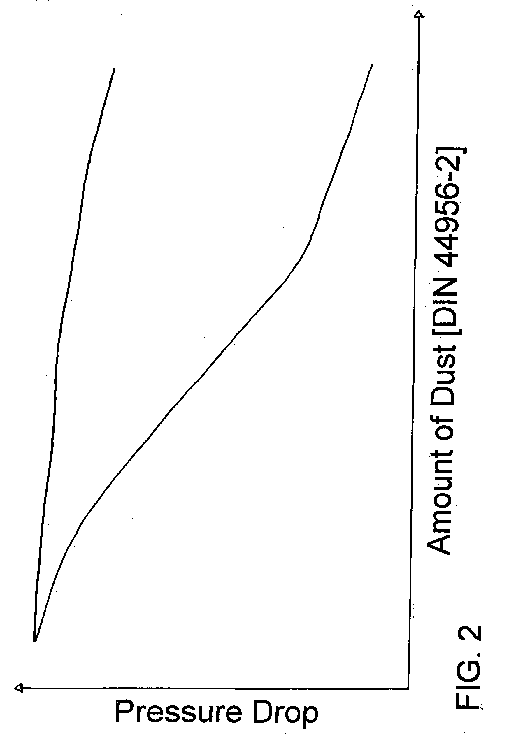
However, as will be shown in detail below (FIG. 2), in this composite filter a relatively high pressure drop across the composite filter occurs.
Further, also the service life time of this filter is low.
Similarly, bulky, highly porous media designed to have large dust holding capacity can be utilized to trap medium to large size dirt particles.
In such a structure, the fibers will crimp with the result that the bulkiness of the tier is further increased.

Method used


Image

  • Composite filter and method of making the same
  • Composite filter and method of making the same
  • Composite filter and method of making the same

Examples


Embodiment Construction

[0055] In the following, and before discussing explicitly discussing the preferred embodiments of the invention, different filter material compositions which suitably used in the present invention are described in greater detail:

[0056] Regarding the discussion below, DIN 44956-2 test has been employed to determine the increase in pressure drop of five different examples of vacuum cleaner bag constructions after dust loading with fine dust at the following levels: 0, 0.5, 1.0, 1.5, 2.0, and 2.5 grams.

[0057] Air Permeability after Fine Dust Loading Test: The dust loading part of the DIN 44956-2 is performed at 0.5 gram increments from 0 to 2.5 g / (m.sup.2.times.s) on seven bags of each sample. However, the pressure drop values are not recorded again. The maximum sustainable air permeability values are then determined on the bags, which had the specified levels of dust loading.

[0058] Standard Vacuum Cleaner Filter Bag Material:

[0059] This material, sometimes referred to as "standard pap...


PUM

PropertyMeasurementUnit
pore diameteraaaaaaaaaa
thicknessaaaaaaaaaa
thicknessaaaaaaaaaa

Abstract

The invention refers to a composite filter for filtering a stream of ambient air comprising at least one non-prebonded upstream tier and one non-prebonded downstream tier, wherein the ratio of absolute pore volume of upstream tier to downstream tier RAPV>2, and the absolute projected fiber coverage of upstream tier and of downstream tier APFC>95%. Further, the invention refers to a method of making such a composite filter comprising the, steps of (a) laying down a filtration material onto a support to form the upstream non-prebonded tier, (b) depositing onto the upstream tier the downstream non-prebonded tier, and (c) bonding the tiers to form a composite filter having a unitary stratified structure.

Description

[0001] The invention relates, to a composite filter for removing solid particles entrained in a stream of ambient air. More specifically, it relates to a composite filter comprising at least one non-prebonded upstream tier and one non-prebonded downstream tier useful for filtering particulates from ambient air.[0002] The term "pre-bonded" means herein that a composition of filter medium, such as thermally bondable fusing fibers or adhesively bindable fibers, is treated in a manner effective to activate the binding mechanism thereby forming a separate, free-standing, cohesive, and typically self-supporting web of that filter composition. Such a pre-bonded web can be mechanically manipulated by such processes as winding on a roll, unwinding from a roll, cutting and the like.[0003] The term "tier" herein means a band formed from non-prebonded filter material into a stratum of unitary stratified structure. In contrast, a "layer" means a separately, prebonded, self-supporting web of filt...

Claims


Application Information

Patent Timeline
Patent Type & Authority Applications(United States)
IPC IPC(8): A47L9/14A47L9/10B01D39/14B01D39/16B01D46/12D04H1/54
CPCA47L9/14B01D39/1615B01D39/1623B01D46/0001B01D46/02Y10T428/27B01D2275/305B01D2279/55Y10S428/903Y10S55/02B01D2275/10Y10T442/668
Inventor SCHULTINK, JANSCHULTINK, BAS
Owner EUROLIFTERS HLDG NV
Learn More