
Data transfer method in radio system

a radio system and data transfer technology, applied in diversity/multi-antenna systems, baseband system details, wireless communication, etc., can solve problems such as inefficient frequency diversity, interference to telecommunications, delay in transmission,

Inactive Publication Date: 2004-05-06
NOKIA CORP
View PDF12 Cites 21 Cited by
  • Summary
  • Abstract
  • Description
  • Claims
  • Application Information

AI Technical Summary

Benefits of technology

[0011] The method and system of the invention provide several advantages. An essential advantage of the invention is that the amount of data to be transmitted to the transmitter to be used for updating a transmit filter can be optimised, thus enabling unnecessary loading of the radio capacity to be avoided.
[0012] The invention is now described in closer detail in connection with the preferred embodiments and with reference to the accompanying drawings, in which
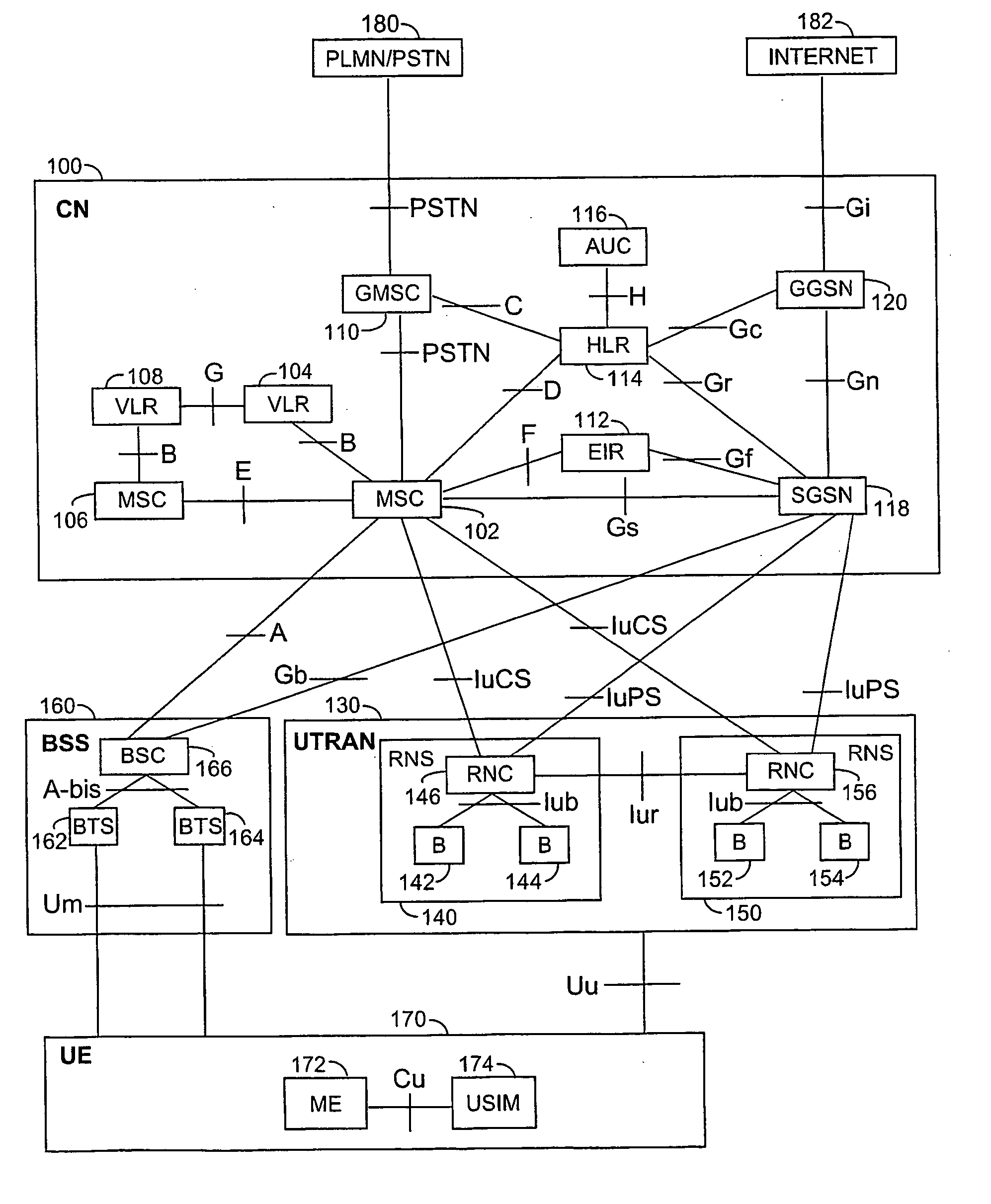
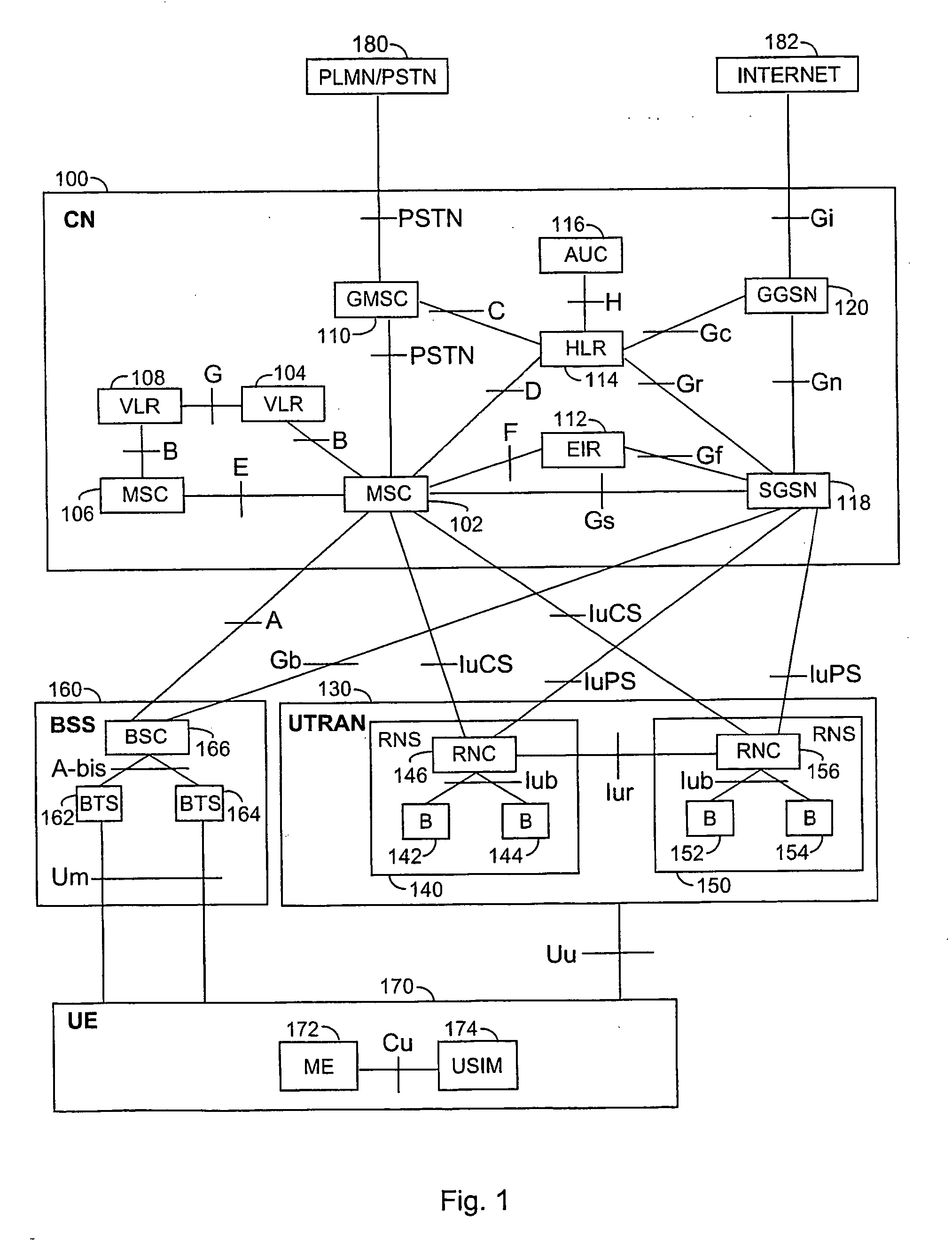
[0013] FIG. 1 is a simplified block diagram showing a telecommunication system,
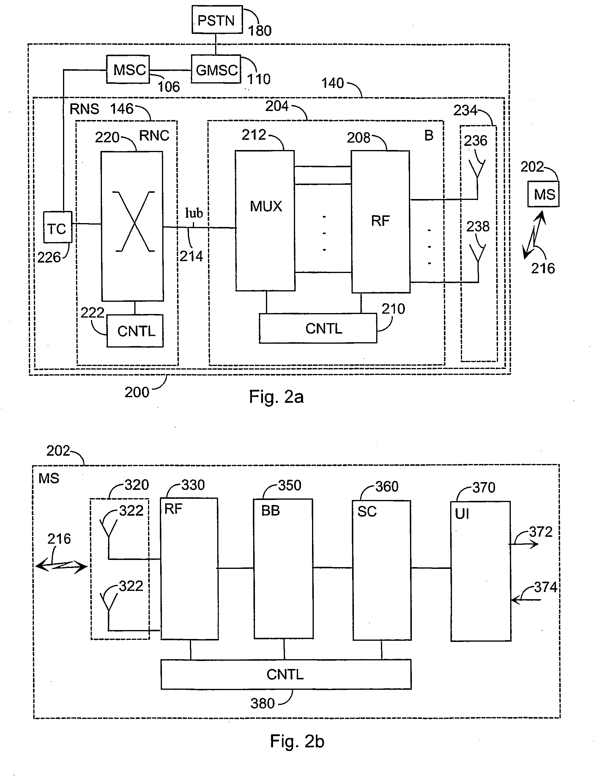
[0014] FIG. 2a is another simplified block diagram showing a telecommunication system,
[0015] FIG. 2b is a simplified block diagram showing terminal equipment, and
[0016] FIG. 3 is a block diagram showing the present solution.

Problems solved by technology

It is generally known that in telecommunication connections, the radio transmission path used for transmitting signals causes interference to telecommunication, the interference typically being functions of time and place.
Interference on a radio transmission path includes radio path fading caused to a radio field by the environment, and interference caused by other radio devices, such as multi-use interference of a radio system.
Time diversity utilizes interleaving and encoding of a signal to be transmitted, but this causes delay to transmission, particularly to slowly fading channels.
In frequency diversity, a signal is simultaneously transmitted at several frequencies; however, frequency diversity is an inefficient method when coherence bandwidth is high.
Particularly in FDD (Frequency Division Duplex) systems, a partial knowledge of the radio path is problematic since the physical channels on the uplink and the downlink transmission path are not identical; consequently, the transmit filter information on a transmitter is usually generated at a receiver.
Drawbacks of the prior art solutions include transfer of unnecessary information and subsequent unnecessary loading of data transfer capacity when the transmit filter information on a transmitter is updated.

Method used


Image

  • Data transfer method in radio system
  • Data transfer method in radio system
  • Data transfer method in radio system

Examples


Embodiment Construction

[0017] Since second generation (2G) radio systems and third generation (3G) radio systems as well as different hybrids thereof, i.e. so-called 2.5G radio systems, are already being used all over the world and under constant development, embodiments will be described in a radio system illustrated in FIG. 1 wherein network elements of different generations coexist. In the description, the 2G radio system is represented e.g. by a GSM (Global System for Mobile Communications). The 2.5G is represented e.g. by a GPRS (General Packet Radio System). The 3G radio system is represented e.g. by a system which is based on the GSM system and which utilizes 3G EDGE (Enhanced Data Rates for Global Evolution) technology, and systems known at least by the names IMT-2000 (International Mobile Telecommunications 2000) and UMTS (Universal Mobile Telecommunications System). The embodiments are not, however, restricted to these systems described as examples but a person skilled in the art can also apply ...


PUM


Abstract

The invention relates to a data transfer method in a radio system utilizing a multiple antenna method, the data transfer method comprising generating, at a receiver, at least part of a change in a variable which contains transmit filter information on a transmitter as compared with a previous value of the variable, transmitting at least part of the change in the variable containing transmit filter information on the transmitter from the receiver to the transmitter and updating, at the transmitter, the transmit filter information on the transmitter on the basis of the received change in the variable containing transmit filter information. The invention further relates to a radio system implementing the method. In the solution, the amount of data used for updating transmit filter information and to be transmitted to a transmitter can be optimised, which enables unnecessary loading of radio capacity to be avoided.

Description

FIELD[0001] The invention relates to a data transfer method in a radio system. The invention relates particularly to a data transfer method wherein more than one antenna is used both at a transmitter and a receiver for transmitting and receiving signals.[0002] It is generally known that in telecommunication connections, the radio transmission path used for transmitting signals causes interference to telecommunication, the interference typically being functions of time and place. Interference on a radio transmission path includes radio path fading caused to a radio field by the environment, and interference caused by other radio devices, such as multi-use interference of a radio system. In connection with moving terminal equipment in particular, the transmission path quality may often vary considerably between different connections and even during a single connection.[0003] A solution to the problem is to use different modes of diversity, such as time diversity, frequency diversity a...

Claims


Application Information

Patent Timeline
IPC IPC(8): H04B7/04H04B7/06H04L25/02H04L25/03
CPCH04B7/0413H04B7/0443H04B7/0634H04L2025/03802H04B7/0654H04L25/0224H04L25/03343H04B7/0643
Inventor TIRKKONEN, OLAVSOININEN, PEKKA
Owner NOKIA CORP
Learn More