Filtration vessel and method for rotary gas compressor system

Inactive Publication Date: 2004-05-13
PARKER INTANGIBLES LLC
View PDF28 Cites 29 Cited by
  • Summary
  • Abstract
  • Description
  • Claims
  • Application Information

AI Technical Summary

Problems solved by technology

These oils are typically "synthetic" oils which are more expensive than typical engine motor oils.
This particular application is challenging due to the large concentration of lube oil as free liquid and aerosols in the fluid stream.
Excessive continual loss of lube oi

Method used


Image

  • Filtration vessel and method for rotary gas compressor system
  • Filtration vessel and method for rotary gas compressor system
  • Filtration vessel and method for rotary gas compressor system

Examples


Embodiment Construction

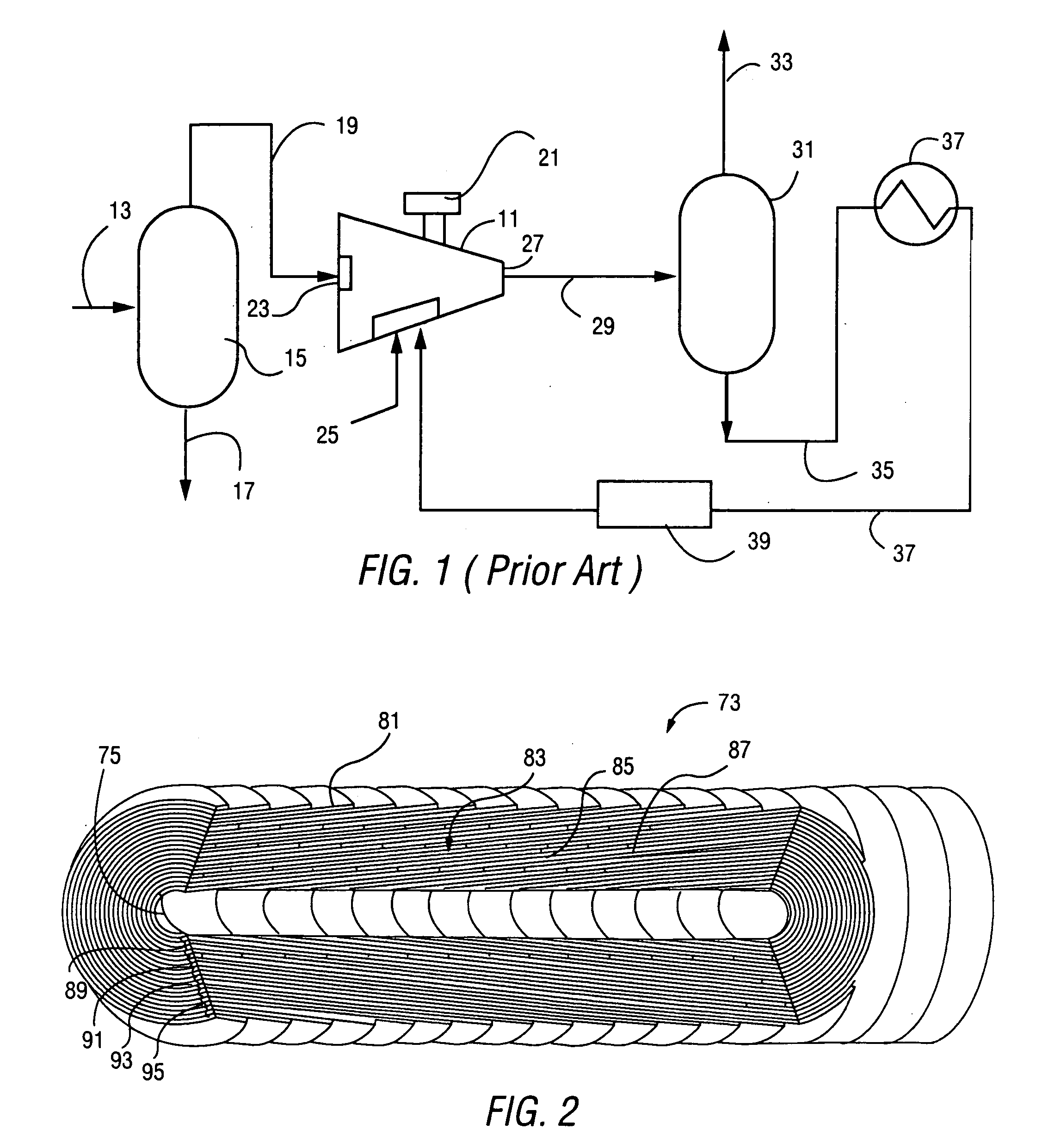
[0030] FIG. 1 shows, in simplified schematic fashion, a prior art gas compression process and compressor system utilizing a rotary screw gas compressor 11. The compressor 11 is a conventional oil flooded rotary screw compressor as will be familiar to those skilled in the industry.

[0031] A raw gas feed stream 13 from a natural gas well or other source is supplied to a scrubber 15 for separating fluids and entrained solids from the raw gas stream 13. The scrubber 15 may be any conventional two or three phase separator which discharges a liquid stream 17 to a disposal reservoir and an essentially dry, low pressure gas stream 19 to the compressor 11. A portion of the gas stream may also be used to power the prime mover 21 which is used to power the compressor 11. However, a variety of other types of engines or electric motors may also be used to drive the compressor 11.

[0032] The compressor 11 receives the low pressure gas through an inlet port 23. A suitable lubricant is supplied to th...


PUM

PropertyMeasurementUnit
Lengthaaaaaaaaaa
Thicknessaaaaaaaaaa
Centrifugal forceaaaaaaaaaa

Abstract

A filtration vessel is shown for use with a rotary screw compressor which receives a compressed liquid/gas mixture from the compressor. The vessel utilizes a first stage vortex knockout region to remove bulk liquids through a circular motion which imposes centrifugal forces on the gas and liquid mixture. A coalescer region located above the vortex knockout region receives the relatively lighter fluids and separates any remaining entrained liquids from the fluids. The discharge from the filtration unit is an essentially liquid free compressed gas. The liquid discharge, in the case of lube oil can be recirculated to the compressor for another cycle.

Description

[0001] BACKGROUND OF THE INVENTION[0002] 1. Field of the Invention[0003] The present invention relates to a device and method for separating oil in a rotary compressor system and, specifically, to a filtration vessel which acts as a lube oil separation coalescer to eliminate liquid particles from a gas stream utilizing a rotary screw compressor.[0004] 2. Description of the Prior Art[0005] Helical lobe rotary compressors, commonly referred to as "screw compressors" are becoming more and more popular in the air compressor, refrigeration and natural gas processing industries. These screw type processors utilize rotors or screws to push or compress gas to a higher pressure. Commonly, two cylindrical rotors are mounted on separate shafts inside a hollow, double-barreled casing. The sidewalls of the compressor casing form two parallel, overlapping cylinders which house the rotors in side by side fashion with their shafts generally parallel to the ground. Helically extending lobes and groo...

Claims


Application Information

Patent Timeline
IPC IPC(8): B01D45/16B01D50/00F04C18/16F04C29/02
CPCB01D45/16B01D50/002Y10S55/17F04C29/026F04C18/16B01D50/20
Inventor BURNS, DAVID J.KROGUE, JOHN A.BORJON, TOMAS I.
Owner PARKER INTANGIBLES LLC
Why Eureka
Try Eureka