Object identification system

Inactive Publication Date: 2004-05-20
HY KO PRODS
View PDF24 Cites 93 Cited by
  • Summary
  • Abstract
  • Description
  • Claims
  • Application Information

AI Technical Summary

Benefits of technology

0012] It is therefore a primary object of the present invention to provide a relatively simple key-blank identification method and apparatus that can identify an identical

Problems solved by technology

The identification of objects that are relatively fungible, but possess minute yet important nuances or details, can be a difficult, tedious and time consuming affair.
As will be readily recognized by those familiar with such enterprises, a failure to accurately identify such objects with regularity can have unintended or undesirable consequences.
However, choosing the correct key-blank can be difficult even for experts in the field.
These hard-to-notice subtleties significantly increase the level of difficulty for all operators of such key replication systems, both inexperienced trainees and experts alike.
If the incorrect key-blank is provided during this process, the key-blank being formed into the duplicate key may not possess the correct longitudinal length, thereby causing a failure.
When this type of failure occurs, the entire process of selecting a key-blank for replication and then mechanically cutting the key must begin again.
Worse still, if the blank has the proper length but does not possess the appropriate thickness, contour, groove or other traits, the failure may not be discovered until the key is actually inserted into the lock.
Such informal and imprecise key-blank identification invariably increases the rate of failures for the duplication process.
These failures often occur, at the expense of the industry and to the extreme dismay of the key holder.
Notably, each of these systems

Method used


Image

  • Object identification system
  • Object identification system
  • Object identification system

Examples


example 2

[0070] The display rack represents another unique aspect of the identification system of the present invention. It is comprised of various individual components. Each of these individual components is assembled together to form a single unit. A flexible system can be created and modified easily by grouping a number of KIDs input stations to a single display rack and / or database (perhaps relying on a computerized network). These units will be integrated with other electronic hardware and software also mentioned elsewhere in this application.

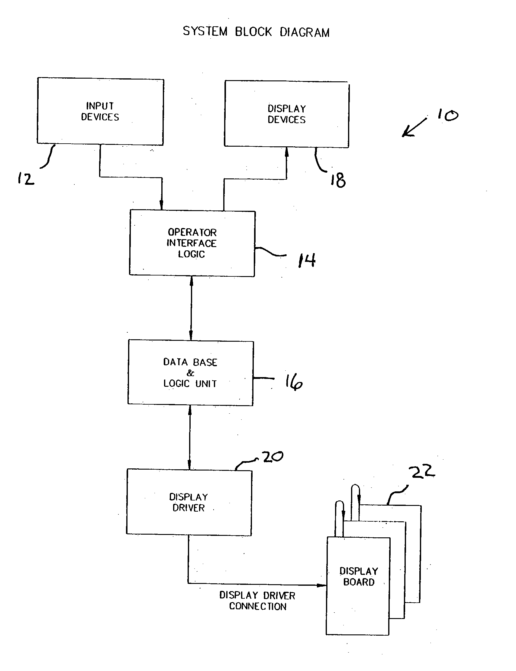
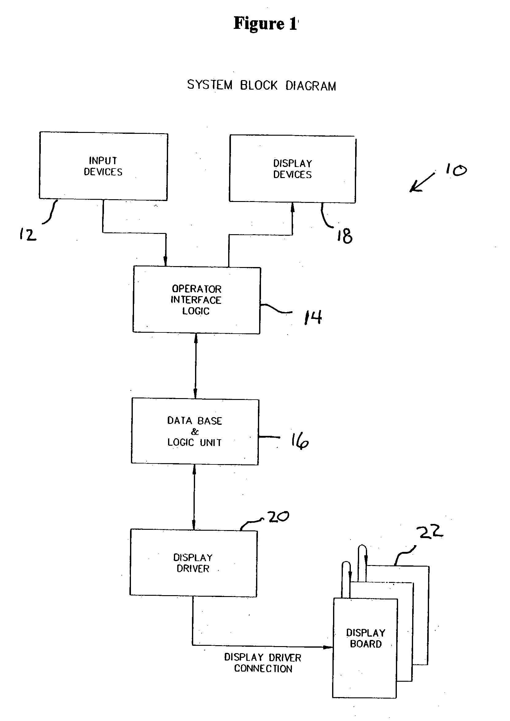
[0071] The basic structure of the Integrated Display Panel is shown in detail in FIG. 15. Essentially, rack 100 comprises an organized grid of light sources 102, such as LEDs, incandescent bulbs or the like. These light sources are selectively wired, in a manner consistent with the description below, and arranged to interact with the system by way of a single display driver connector port 104. Individual product items 106 can be stored and / or disp...

example 3

[0083] The identification system of the present invention relies upon the aforementioned database means for comparing specific observed traits of an unknown object with accumulated data concerning those same traits for a wide range of known items. As such, the database means forms an indispensable part of the inventive system. The data itself is organized into a number of standardized fields which correspond direct to the specified trait being inputted by the user.

[0084] As mentioned above, the programming required by the database and associated software applications can be achieved using known programming languages and techniques. The software could be implemented using database platforms and operating systems. Alternatively, the program could be specially written utilizing object-oriented or other known programming strategies and computer codes such as Active X, XML, C+, etc. Artificial intelligence concepts could be implemented so that the system would essentially adapt to learn ...


PUM


Abstract

A system and method for identifying objects possessing minute but significant details is described. At its core, the system includes a user interface, means for comparatively identifying the object and means for displaying results. Notably, because the system does not rely upon highly specialized or complex equipment, the invention is expected to have particular applicability in a wide variety of every-day situations. Moreover, the system is explicitly designed for user friendliness, so as to eliminate that need for extensive training for any prospective user of the system. The system should have particular applicability in key blank identification and key duplication processes.

Description

[0001] This invention relates generally to the field of systems for identifying objects and, more particularly to systems for utilizing electronic means for identifying key blanks that are functionally compatible with an unknown key for use in a key duplication system. This application is related to, and claims all benefits under of 35 U.S.C. 119(e), the Provisional Patent Application Serial No. 60 / 452,893 entitled "OBJECT IDENTIFICATION SYSTEM" and filed on Mar. 7, 2003 and the Provisional Patent Application Serial No. 60 / 400,772 entitled "IDENTIFICATION SYSTEM" and filed on Aug. 2, 2002.BACKGROUND OF INVENTION[0002] The identification of objects that are relatively fungible, but possess minute yet important nuances or details, can be a difficult, tedious and time consuming affair. As will be readily recognized by those familiar with such enterprises, a failure to accurately identify such objects with regularity can have unintended or undesirable consequences.[0003] The identificat...

Claims


Application Information

Patent Timeline
IPC IPC(8): B23C1/00B23C1/16G06F17/30G09G5/00
CPCG07F11/70G06F17/30398G06F16/245G06F16/2428G06F3/0482G06F3/04842G06F3/04847
Inventor BASS, MICHAEL A.HANISH, MICHAEL B.MUTCH, WILLIAM R.RYAI, RICHARD WM. SR.THOMPSON, CHESTER O. D. IIISHANER, DAVID E.WORK, JOSEPH M. III
Owner HY KO PRODS
Why Eureka
Try Eureka