Swivel

a swivel and splint technology, applied in the field of swivels, can solve the problems of swivels of this type, time-consuming and expensive manufacturing, and devices that are separate from fluid transfer, so as to reduce the cost of manufacturing, simplify the design, and reduce the time of manufacturing

Inactive Publication Date: 2004-05-27
INTERCEDO IND AUTOMATION
View PDF12 Cites 5 Cited by
  • Summary
  • Abstract
  • Description
  • Claims
  • Application Information

AI Technical Summary

Benefits of technology

[0011] By the invention a simpler and cheaper design is obtained. The fluids and the electricity are transferred by principally the same devices, which means that the service is greatly simplified and the service time shortened. Besides, the over-all life-span is greatly improved.
[0012] The exchange of possibly damaged hoses or cables is facilitated by the use of quick-couplings for them in the members.
[0013] The number of fluids and signals that can be transferred can be increased in the design according to the invention. This may be of importance for example at the use of industrial robots in foundries, where for example cooling liquid and lubricant may have to be transferred in the swivel connector. A marked productivity increase may result.

Problems solved by technology

A known problem with this type is the sealing between the members and around the grooves.
These devices, which are separate from the fluid transfer, are susceptible of wear and negative influences of dirt, dust and the like.
A swivel of this type is relatively complicated and therefore time-consuming and expensive to manufacture.
In spite of this the number of different fluids that can be transferred is limited.
Due to the complicated construction it is difficult to service the device, and the life-span is relatively short.

Method used


Image

  • Swivel
  • Swivel

Examples


Embodiment Construction

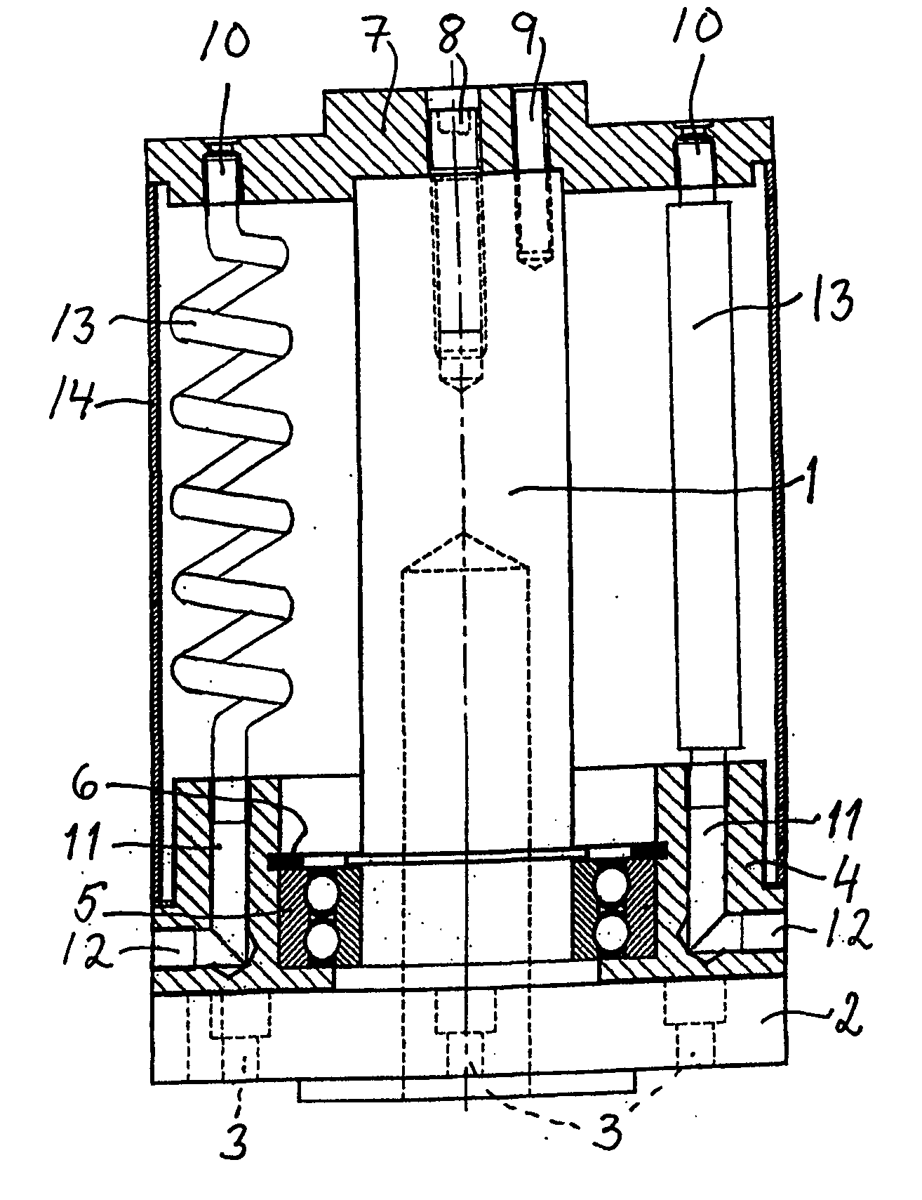
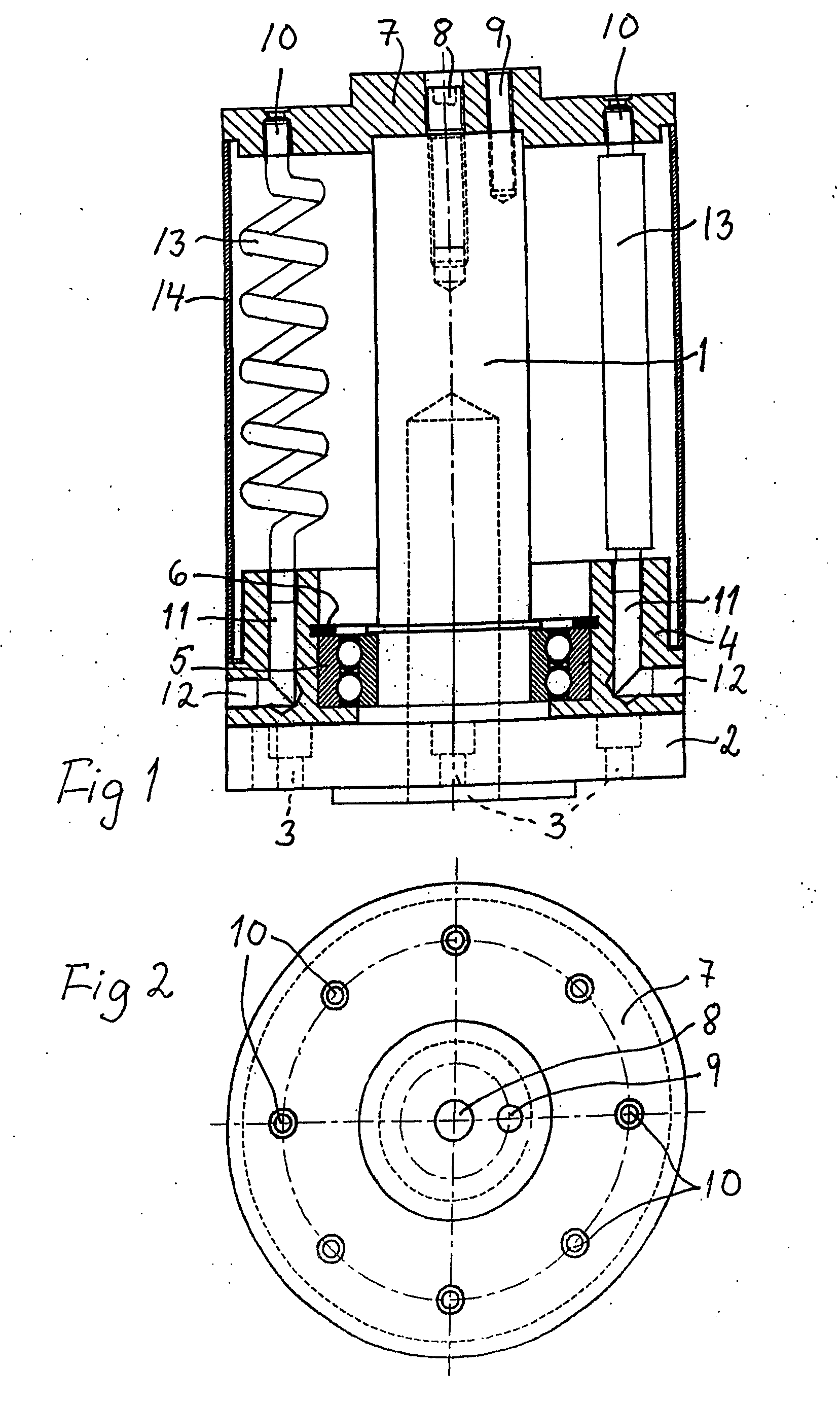
[0017] A swivel for example for an industrial robot is shown in the drawing.

[0018] A central shaft 1 is attached to a base plate 2, which has screw holes 3 for its mounting to further parts (not shown) of the robot.

[0019] The lower connection ring 4 is rotatably journalled in relation to the shaft 1 by means of a bearing 5, held in position by a spring ring 6.

[0020] A cover 7 forming an upper connection is attached to the shaft 1 by means of a central screw 8. Alternatively, a quick-coupling may be used for this purpose, which is an advantage in a service situation. The angular position of the cover 7 in relation to the shaft 1 can be set by a pin 9 in corresponding holes in the shaft 1 and the cover 7.

[0021] The cover 7 is provided with a number of through connection holes 10, in the shown example eight holes, for compressed air, cooling water, lubricant, electric power, or control signals as typical examples of operating or controlling media to be transferred by the swivel.

[0022] ...


PUM


Abstract

The invention discloses a swivel comprising two coaxial, mutually rotatable members is provided with means for transferring operating and / or controlling media or the like between the members. The means can be flexible hoses or cables connected between the members. The hoses or cables are connected to the members by means of quick-couplings.

Description

[0001] The present invention relates to a swivel comprising two coaxial, mutually rotatable members and having means for transferring operating and / or controlling media or the like between the members.[0002] A typical use for a swivel of the above type is in an industrial robot, and the invention will be exemplified by reference to this use. However, the invention is not so limited; it may be utilized in many applications within the scope of the appended claims.[0003] In a swivel media like compressed air, cooling liquid, lubricant, electric power, and / or control signals, i e generally fluids and or electricity, are to be transferred between the two coaxial, mutually rotatable members.[0004] With regard to fluid transfer the two members are rotating against each other, and the cooperating surfaces of the members are provided with mutually corresponding circular grooves, so that fluid may be transferred from one member to the other irrespective of their mutual angular position. A kno...

Claims


Application Information

Patent Timeline
Patent Type & Authority Applications(United States)
IPC IPC(8): F16L39/06B25J19/00
CPCF16L39/06F16G15/08
Inventor SRANKA, JAROSLAV
Owner INTERCEDO IND AUTOMATION
Why Eureka
Try Eureka