
Method and apparatus for eliminating and compensating thermal transients in gas analyzer

a gas analyzer and thermal transient technology, applied in the direction of material thermal analysis, material analysis using sonic/ultrasonic/infrasonic waves, material thermal analysis, etc., can solve the problems of reducing measurement accuracy, affecting the detection effect, etc., to achieve good thermal conductivity

Active Publication Date: 2006-07-04
INSTRUMENTARIUM CORP
View PDF7 Cites 4 Cited by
  • Summary
  • Abstract
  • Description
  • Claims
  • Application Information

AI Technical Summary

Benefits of technology

"The present invention provides a gas analyzer that overcomes the shortcomings of prior-art techniques by eliminating offset and drift caused by internal thermal transients. The invention achieves this by using a simple and cheap mechanical thermal flow design that eliminates the need for expensive thermopile detectors. The invention also includes a thermal mass that is in thermal contact with the measuring volume and the radiation source, and a heat sink for the radiation source. The invention is designed to meet the requirements of electrically sensitive equipment used in demanding hospital environments. The invention is based on minimizing the static and dynamic state thermal gradients over the thermal detector(s) in the gas analyzer."

Problems solved by technology

A characteristic of a thermopile detector is that thermal gradients or transients in its external housing, noticeable especially in small analyzers with small thermal mass, will cause an offset error in the detector signal, which degrades measurement accuracy.
It is therefore easy to understand that even small temperature gradients in the thermopile housing may cause considerable measurement errors.
Static state thermal gradient appears as temperature difference between any two points in the analyzer and when it appears over the thermopile detector it causes an offset error into the detector signal.
When the ambient temperature or the internal temperature of the analyzer changes the thermal flow in the analyzer causes a variable temperature difference between any two points in the analyzer and when it appears over the thermopile detector it causes a variable offset error into the detector signal.
Such errors occur with a change of the external housing temperature after, e.g., a cold start-up of the analyzer or due to a change in the ambient temperature.
This further means that no thermal gradient can be allowed within the detector housing in spite of the relatively high heat flow and small thermal mass of the small sized analyzer.
A characteristic of the thermopile is that with a change of its external housing temperature after, e.g., a cold start-up of the analyzer or due to an ambient temperature change the detector output will contain a transient error which degrades measurement accuracy over the duration of the transient state.
Measuring the temperature in one or even few points of the detector case or its thermally conductive housing does not indicate the source or the direction of heat flow accurately enough to predict whether the temperature change is caused by ambient temperature change, internal thermal transient caused by e.g. a cold start-up of the analyzer or e.g. a fan cooling the one side of the sensor.
Adding multiple temperature sensors in the gas analyzer body makes the analyzer uneconomical and functioning complicated through heavy computing.

Method used


Image

  • Method and apparatus for eliminating and compensating thermal transients in gas analyzer
  • Method and apparatus for eliminating and compensating thermal transients in gas analyzer
  • Method and apparatus for eliminating and compensating thermal transients in gas analyzer

Examples


Embodiment Construction

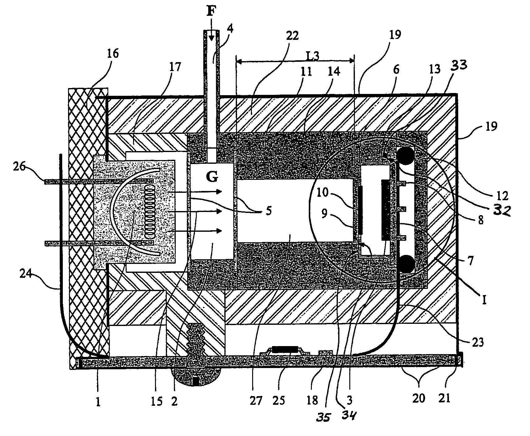
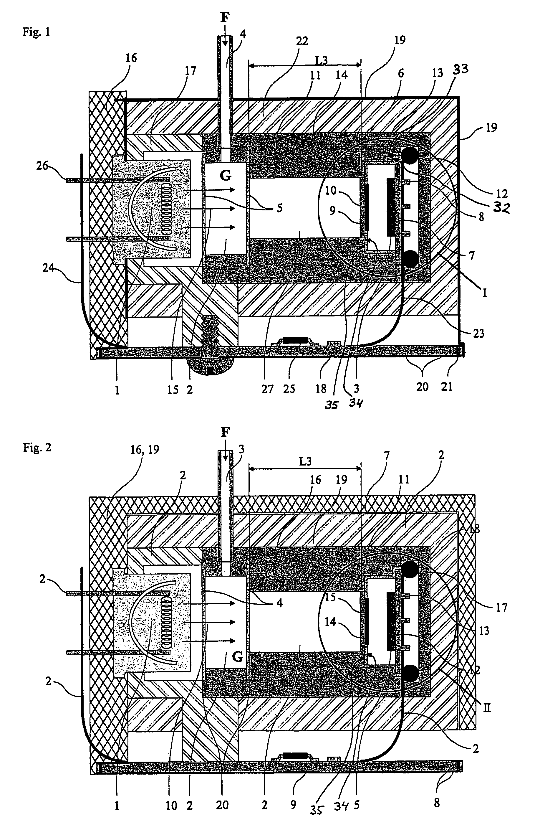
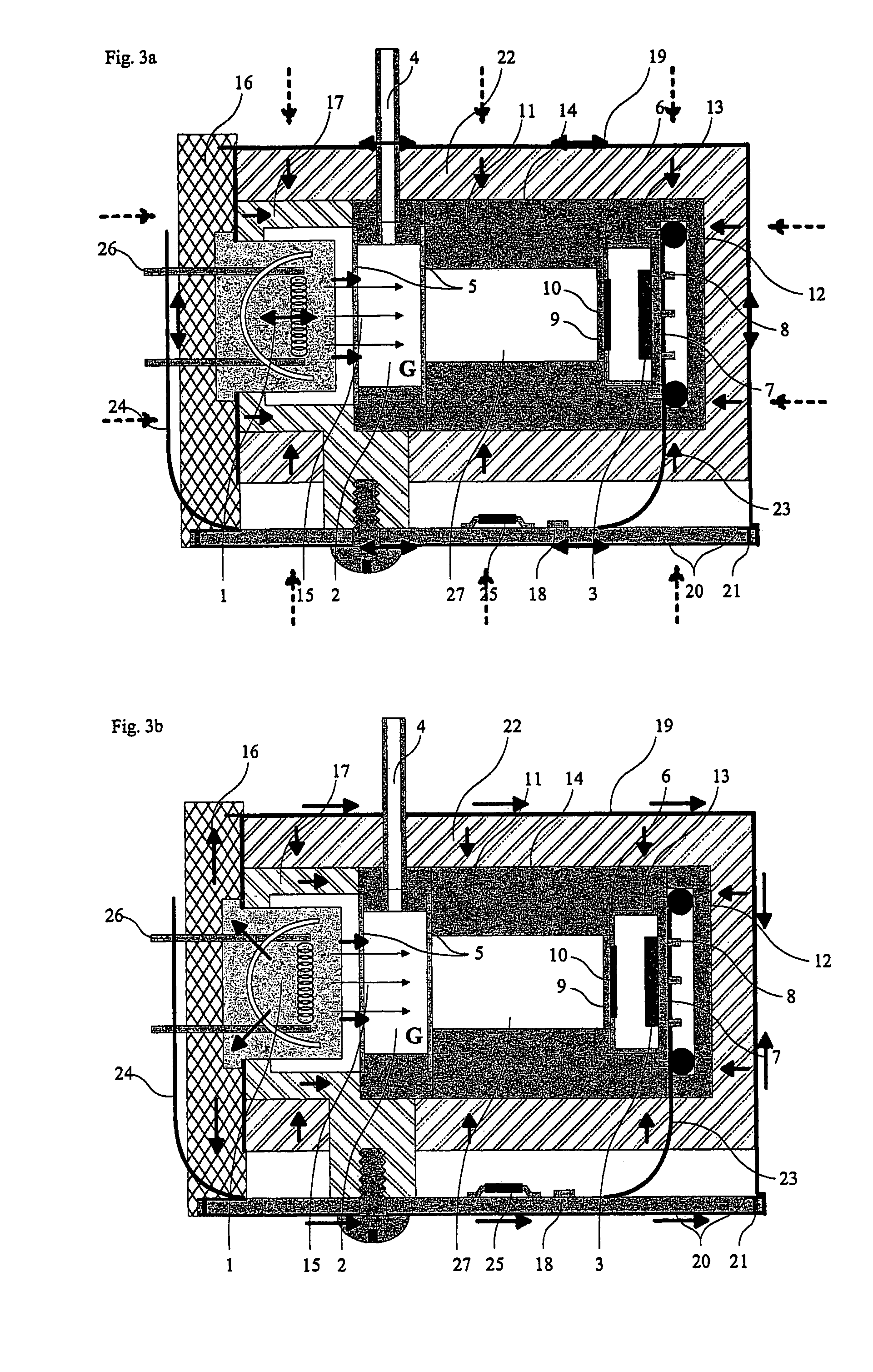
[0024]The small sized or miniature gas analyzers for analyzing, e.g. measuring the concentration of one or several gas components are shown in figures. The analyzer comprises a measuring volume 2, made of metal, e.g. aluminum or copper or a plastic or a polymer, between the infrared source 1 and the detector(s) 3. The measuring volume has connections 4 for input and output flow (not shown) of a sample gas mixture G. The measuring volume 2 can be a closed measuring chamber. Alternatively the measuring volume 2 can be a generally open space, i.e. a substantially non-bordered room open to ambience, whereupon the flow F of the gas mixture G into and out of this non-bordered room is caused e.g. by natural movements in the surrounding atmosphere. The measuring volume has first and second ends 5 transparent to radiation. Concerning the embodiment provided with the measuring chamber these transparent ends are typically two windows forming the ends of the volume 2. The two windows forming sa...


PUM

PropertyMeasurementUnit
thicknessaaaaaaaaaa
thicknessaaaaaaaaaa
temperatureaaaaaaaaaa

Abstract

The invention concerns a gas analyzer comprising: a measuring volume (2), a radiation source (1) for providing a beam to pass said measuring volume; a heat sink (16) for said radiation source; at least one thermal detector (3) having a hot junction within a support structure and receiving the radiation and a cold junction for reference within the same support structure and protected from said radiation; at least one optical bandpass filter (9) between said hot junction and said radiation source; and a thermal mass (11), which is formed of a material having high thermal conductance. The thermal mass has a cavity with a bottom step (34) and a rim (32), and a first length therebetween. The support structure has a frontal edge (35) and a base plate lip (33), and a second length therebetween. There is a radial gap between the thermal mass and the support structure. Press means urge said support structure in the cavity, whereupon a more efficient thermal contact is either between said frontal edge and said bottom step, or between said base plate lip and said rim. A first thermal barrier (17) is between the heat sink and the thermal mass, and a second thermal barrier (22) surrounds the thermal mass. A shield (19) formed of a material having high thermal conductance covers said second thermal barrier and is in thermal contact with said heat sink.

Description

FIELD OF THE INVENTION[0001]The invention relates a gas analyzer and a method for determining the concentration of at least one gas component present in a sample gas mixture. The arrangement comprises a radiation source for providing a beam of electromagnetic radiation; a heat sink for said radiation source; at least one thermal detector having an active radiation detecting sensor element in a support structure, and a reference sensor element within the same support structure and protected from said radiation, said thermal detector generating an output signal indicative of a property of said at least one gas component; and at least one optical bandpass filter between said active radiation detecting sensor element and said radiation source; as well as a thermal mass: formed of a material having high thermal conductance; having a cavity; being at least in partial thermal contact with said support structure inside said cavity; and extending towards the radiation source.BACKGROUND OF TH...

Claims


Application Information

Patent Timeline
Patent Type & Authority Patents(United States)
IPC IPC(8): G01N25/00G01N21/27G01N21/35G01N21/61
CPCG01N21/3504G01N21/274G01N2201/12792G01N2201/023G01N2201/1211G01N21/61
Inventor WECKSTROM, KURTHAVERI, HEIKKIHIETALA, MIKA
Owner INSTRUMENTARIUM CORP
Learn More