
Nozzle ring with non-uniformly distributed airfoils and uniform throat area

a technology of airfoil and nozzle ring, which is applied in the direction of engine fuction, motors, liquid fuel engines, etc., can solve the problems of unfavorable vibration of the rotor blades

Inactive Publication Date: 2014-09-25
ABB TURBO SYST
View PDF6 Cites 10 Cited by
  • Summary
  • Abstract
  • Description
  • Claims
  • Application Information

AI Technical Summary

Benefits of technology

The patent improves the efficiency and durability of a turbine stage and rotor by designing better vanes that increase specific flow capacity and reduce fuel costs. This design also allows for more compact and cost-effective products. Additionally, the nozzle ring position can be simplified, resulting in a more efficient and faster to install and repair design.

Problems solved by technology

Variations in throat area between adjacent vanes can provide undesirable aero-mechanical excitation pressure forces which may lead to undesirable vibration of the rotor blades disposed downstream from the nozzle.
An issue of the mentioned segmented nozzle ring design is that the nozzle throat area can differ from one segment to the other.

Method used


Image

  • Nozzle ring with non-uniformly distributed airfoils and uniform throat area
  • Nozzle ring with non-uniformly distributed airfoils and uniform throat area
  • Nozzle ring with non-uniformly distributed airfoils and uniform throat area

Examples


Embodiment Construction

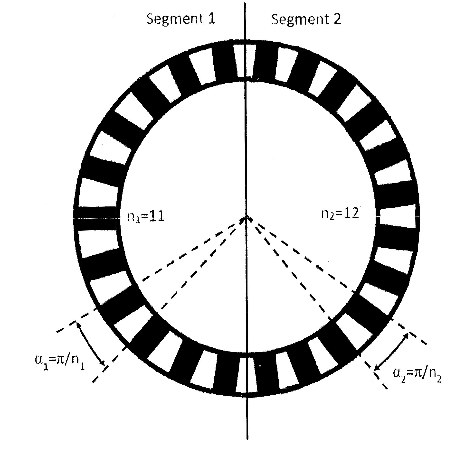
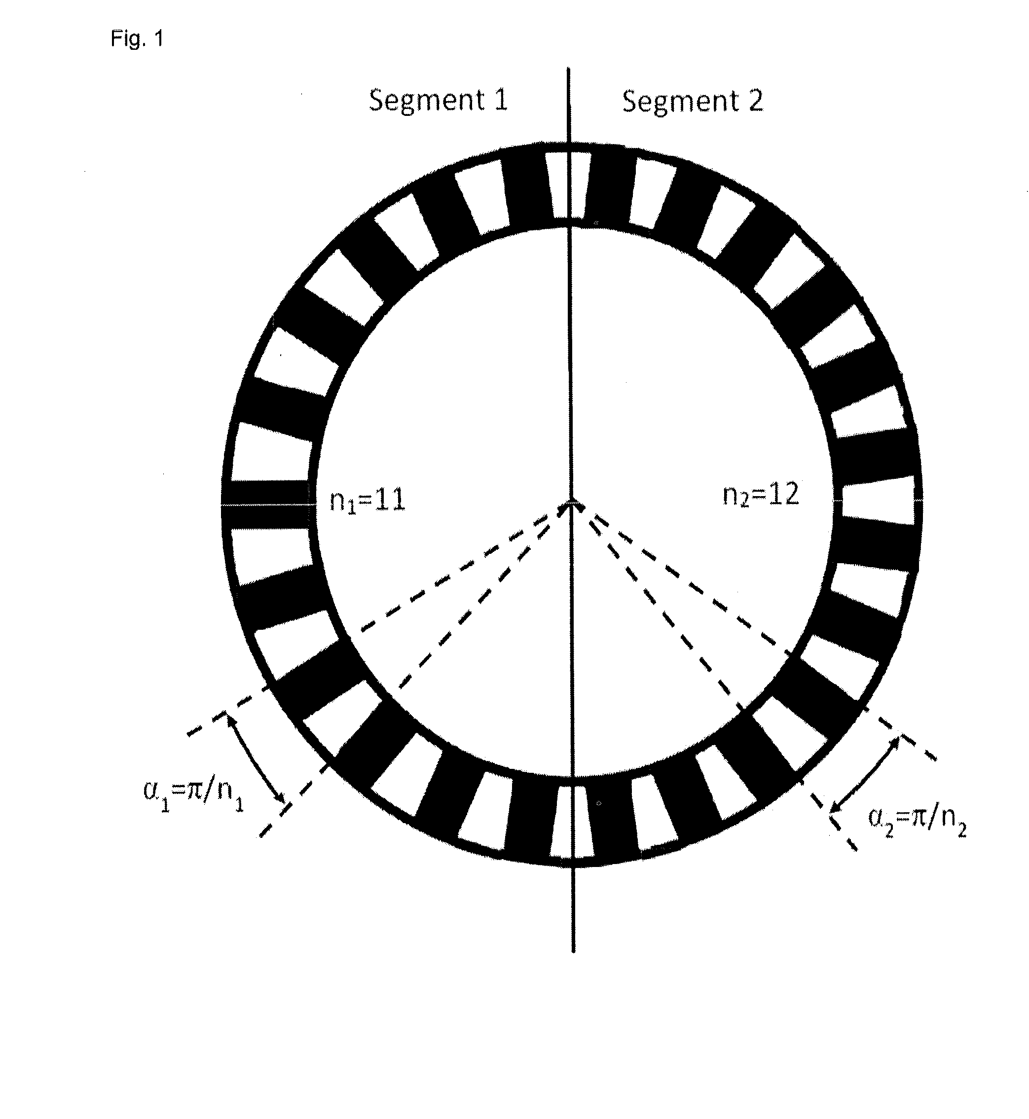
[0017]Exemplary embodiments of the present disclosure provide a segmented nozzle ring including different numbers of nozzle vanes per segment which have uniform individual throat areas between the adjacent vanes.

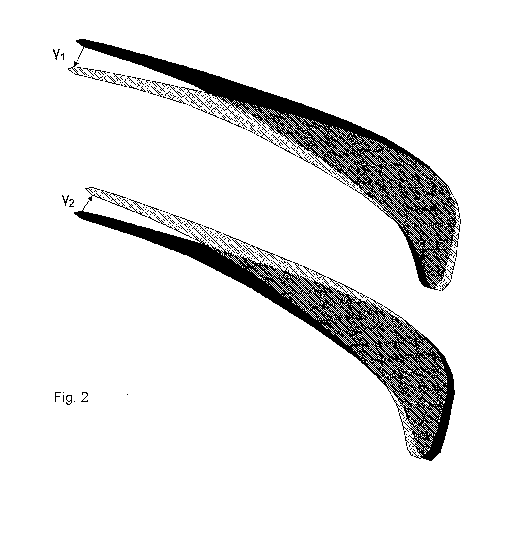
[0018]For the segmented nozzle ring according to an exemplary embodiment of the disclosure, the throat area between neighboring vanes can be the same for each segment which is achieved by rotation (i.e., opening or closing of the throat area) of the individual vane compounds belonging to the different segments. The resulting uniform throat area can lead to a uniform exit flow angle of the nozzle and a uniform inlet flow angle of the rotor.

[0019]Based on that, high-cycle fatigue excitations of the rotor caused by the non-uniform flow can be eliminated, the thermodynamic efficiency of the turbine stage can be improved, and the nozzle ring need not be arranged in a fixed position relative to the gas inlet casing.

[0020]The thermodynamic efficiency of the turbine stage as well as...


PUM


Abstract

A segmented nozzle ring is disclosed having a throat area between neighboring vanes that is the same for each segment which is achieved by rotation (i.e., opening or closing of the throat area) of the individual vane compounds belonging to the different segments. The resulting uniform throat area leads to a uniform exit flow angle of the nozzle and a uniform inlet flow angle of the rotor. As a result, high-cycle fatigue excitations of the rotor caused by the non-uniform flow can be eliminated, the thermodynamic efficiency of the turbine stage can be improved, and the nozzle ring need not be arranged in a fixed position relative to the gas inlet casing.

Description

RELATED APPLICATION(S)[0001]This application claims priority under 35 U.S.C. §119 to European Patent Application No. 13159879.9 filed in Europe on Mar. 19, 2013, the entire content of which is hereby incorporated by reference in its entirety.FIELD[0002]This disclosure relates to exhaust gas turbines of turbochargers for combustion engines, and for example, to a nozzle ring for guiding the exhaust gas flow in such a gas turbine.BACKGROUND INFORMATION[0003]A known exhaust gas turbines of turbochargers for combustion engines with fixed turbine geometry includes a turbine nozzle for channeling the exhaust gases to a plurality of rotor blades. The turbine nozzle includes a plurality of circumferentially spaced stator vanes fixedly joined at their roots and tips to annular, radially inner and outer supporting rings. In case of a radial or mixed flow turbine, the stator vanes of the nozzle ring are fixed at their roots and tips to annular supporting rings being arranged next to each other ...

Claims


Application Information

Patent Timeline
Patent Type & Authority Applications(United States)
IPC IPC(8): F02B37/22
CPCF02B37/22F01D9/041F05D2220/40F05D2260/961
Inventor SENN, STEPHAN M.
Owner ABB TURBO SYST
Learn More