Brushless DC motor with control electronics motor assembly

a technology of control electronics and motors, which is applied in the direction of electrical devices, dynamo-electric machines, support/enclose/cases, etc., can solve the problems of increasing the length or other external dimensions of the motor assembly, the motor assembly is often larger and bulkier than desirable for many applications, and the motor assembly is often large and bulky. , to achieve the effect of low cost and compactness, good motor performance and high torqu

Active Publication Date: 2018-04-05
SIMPLEX MOTION
View PDF6 Cites 0 Cited by
  • Summary
  • Abstract
  • Description
  • Claims
  • Application Information

AI Technical Summary

Benefits of technology

[0008]Accordingly, a first object of the invention is to provide a very compact motor assembly with a brushless DC motor and control electronics, which provides substantially better performance, as regards output torque, power / volume ratio and efficiency, for a considerably lower price than what has been possible with the previously known motor assemblies.
[0010]Thanks to the fact that the motor assembly according to the invention uses an integrated control electronics with magnetic field sensors to determine the angular position of the rotor in a brushless DC motor which, according to the invention, has been selected to be an external rotor motor, a very inexpensive and compact motor assembly with good motor performance can be realized. Thanks to the external rotor motor, the motor assembly according to the invention can be provided with a sufficiently high torque to eliminate the need for a gearbox, which results in a simpler and cheaper design and smaller external dimensions. Furthermore, thanks to the external rotor motor, the motor assembly according to the invention obtains a very high efficiency, enabling a higher output power and lower energy consumption. Thanks to the arrangement of magnetic field sensors in combination with an external rotor motor, the angular position of the rotor can be determined by measuring radial magnetic leakage flux through the external rotor, i.e. external relative to the stator, thus enabling the whole measurement arrangement to be simplified and the control electronics to be designed in a more compact fashion, so that the motor assembly according to the invention can be given very small external dimensions in relation to its motor performance.

Problems solved by technology

A disadvantage of many of the previously known motor assemblies with brushless DC motors and integrated control electronics is that the motor assemblies are often larger and bulkier than desirable for many applications.
Another reason is that many of the previously known motor assemblies have a design which requires a complicated and space-consuming measurement arrangement, usually disposed at the shaft end of the motor, to be able to measure the angular position of the rotor and / or bulky control electronics, which considerably increases the length or other external dimensions of the motor assembly.

Method used


Image

  • Brushless DC motor with control electronics motor assembly
  • Brushless DC motor with control electronics motor assembly
  • Brushless DC motor with control electronics motor assembly

Examples


Embodiment Construction

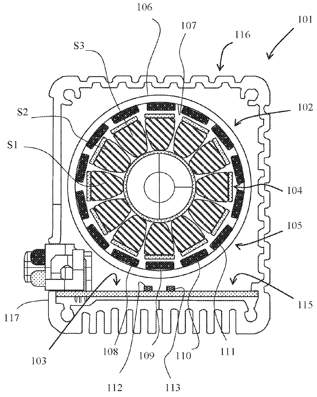
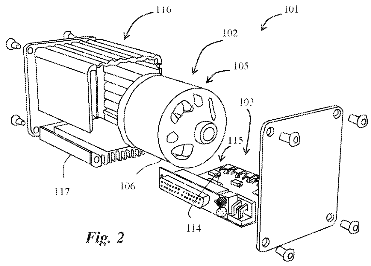
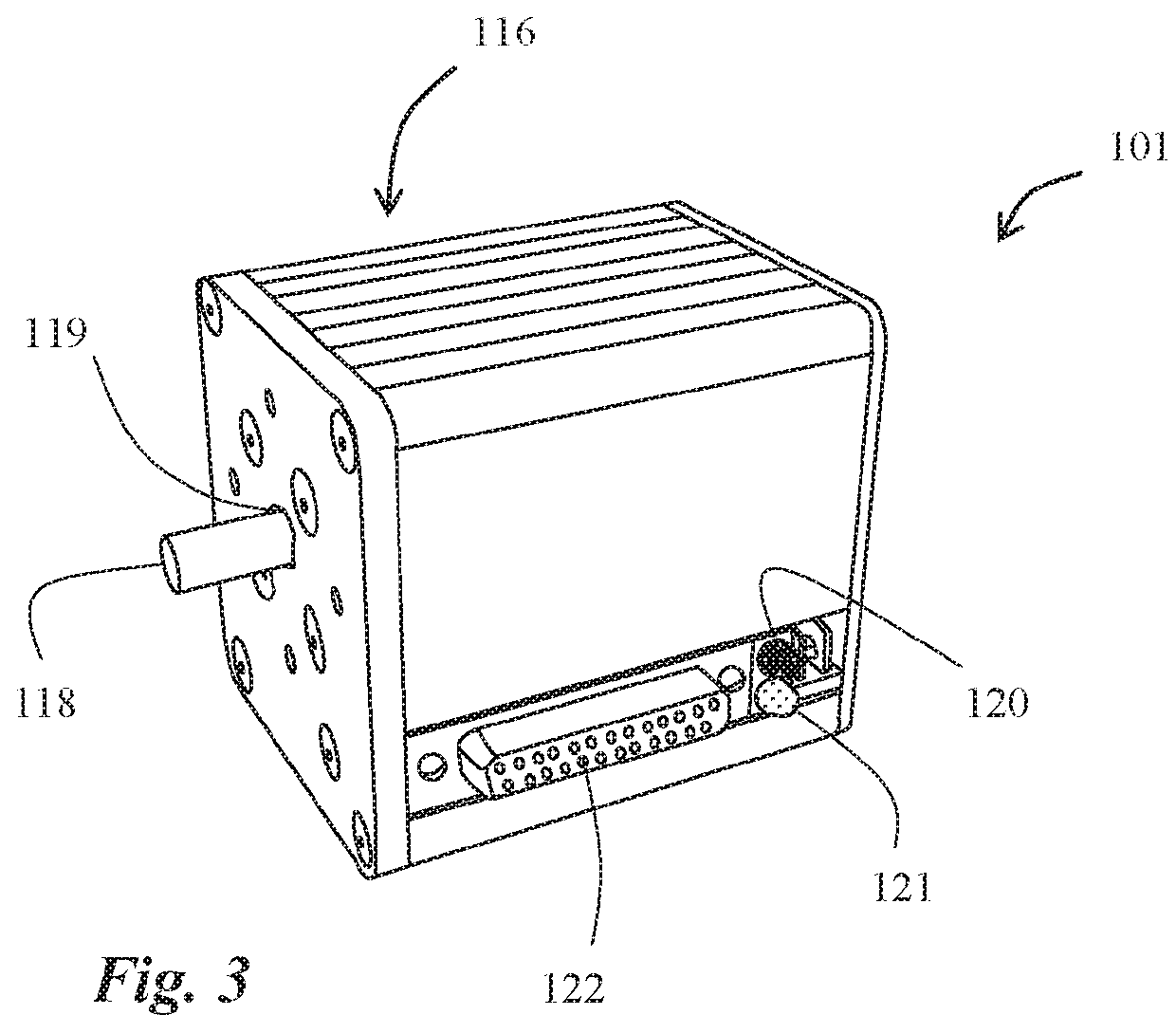
[0015]In the following, a number of embodiments of the invention will be described in detail with reference to the accompanying drawings. In the drawings, FIG. 1 shows a schematic representation of a cross-section of a motor assembly according to the invention. FIG. 2 is a perspective view of a motor assembly according to a preferred embodiment of the invention, in a partially exploded condition, whereas FIG. 3 shows the same motor assembly in an assembled condition.

[0016]The motor assembly 101 comprises a brushless DC motor 102 with control electronics 103. A brushless DC motor can also be defined as an alternating current motor with permanent magnets on the rotor and electronic commutation.

[0017]The control electronics 103 of the motor assembly comprises at least two magnetic field sensors adapted to measure magnetic flux from magnetic poles on a rotor in the brushless DC motor 102. The magnetic field sensors are adapted to determine an angular position of the rotor, based on the ...


PUM


Abstract

A motor assembly, comprising a brushless DC motor with control electronics which comprises at least two magnetic field sensors adapted to measure magnetic flux from magnetic poles on a rotor in the brushless DC motor. The magnetic field sensors are adapted to determine an angular position of the rotor, with the purpose of controlling the current to the brushless DC motor based on the determined angular position. The brushless DC motor is an external rotor motor comprising an internal stator, and an external rotor having a periphery and an inside, which exhibits a plurality of permanent magnets disposed at regular intervals along the inside to provide the magnetic poles. The magnetic field sensors are disposed at a distance from each other in the proximity of the periphery to measure the magnetic flux leaking radially through the external rotor from the permanent magnets on the inside.

Description

TECHNICAL FIELD[0001]The present invention relates to a motor assembly comprising a brushless DC motor with control electronics.BACKGROUND OF THE INVENTION[0002]In many applications where electric motors are used, a smooth rotation of the rotor of the electric motor, and therefore also a precise control of the rotor current and the wave shape thereof, are required. To be able to achieve a sufficiently precise control, it is required that the angular position of the rotor can be detected in an accurate manner. Usually, in conventional electric motors, an angle sensor or resolver, together with associated electronics, are used for determining the angular position. The angle sensors detect mechanical movement and convert the detected movement into electric signals. Optical pulse sensors and absolute angle sensors are two commonly occurring types of angle sensors.[0003]To be able to achieve a precise current control and smooth rotation in so-called brushless DC motors, i.e. alternating ...

Claims


Application Information

Patent Timeline
Patent Type & Authority Applications(United States)
IPC IPC(8): H02P6/16H02K11/33H02K11/35H02K29/08H02K5/18
CPCH02P6/16H02K11/33H02K11/35H02K29/08H02K5/18H02K5/225
Inventor LINDER, JOHAN
Owner SIMPLEX MOTION
Why Eureka
Try Eureka