Drill and production method thereof

Inactive Publication Date: 2004-05-27
MITSUBISHI MATERIALS CORP
View PDF19 Cites 49 Cited by
  • Summary
  • Abstract
  • Description
  • Claims
  • Application Information

AI Technical Summary

Problems solved by technology

If this type of ridge section R remains, since the quality of discharge decreases due to chips becoming caught on this ridge section, an additional step is required to remove this ridge section R, thereby resulting in a considerable decrease in drill production efficiency.
Consequently, drilling end 1' is unable to be guided in a stable manner with respect to force from direction X in FIGS. 27A and 27B, resulting in the occurrence of runout in drilling end 1' and causing problems such as increased surface roughness of the inner wall surface of the formed machined hole K or chipping cutting edge 3 due to contact with the wall surface of machined hole K (and breaking drilling end 1' in cases of particularly excessive runout).
As a result, chips are easily clogged in chip discharge groove 2, and when this clogging becomes prominent, it may lead to breakage of drilling end 1'.
However, in the case of a drill such as this for drilling deep holes in which the total length of bit section I' is long, since the distance over which chips generated by cutting edge 3 are discharged through chip discharge groove 2 also becomes longer, chips easily become clogged in chip discharge groove 2.
Moreover, since drill rigidity and strength also tend to decrease as the total length of bit section 1' increases, the drill is increasingly susceptible to breakage due to clogging of chips in chip discharge groove 2.
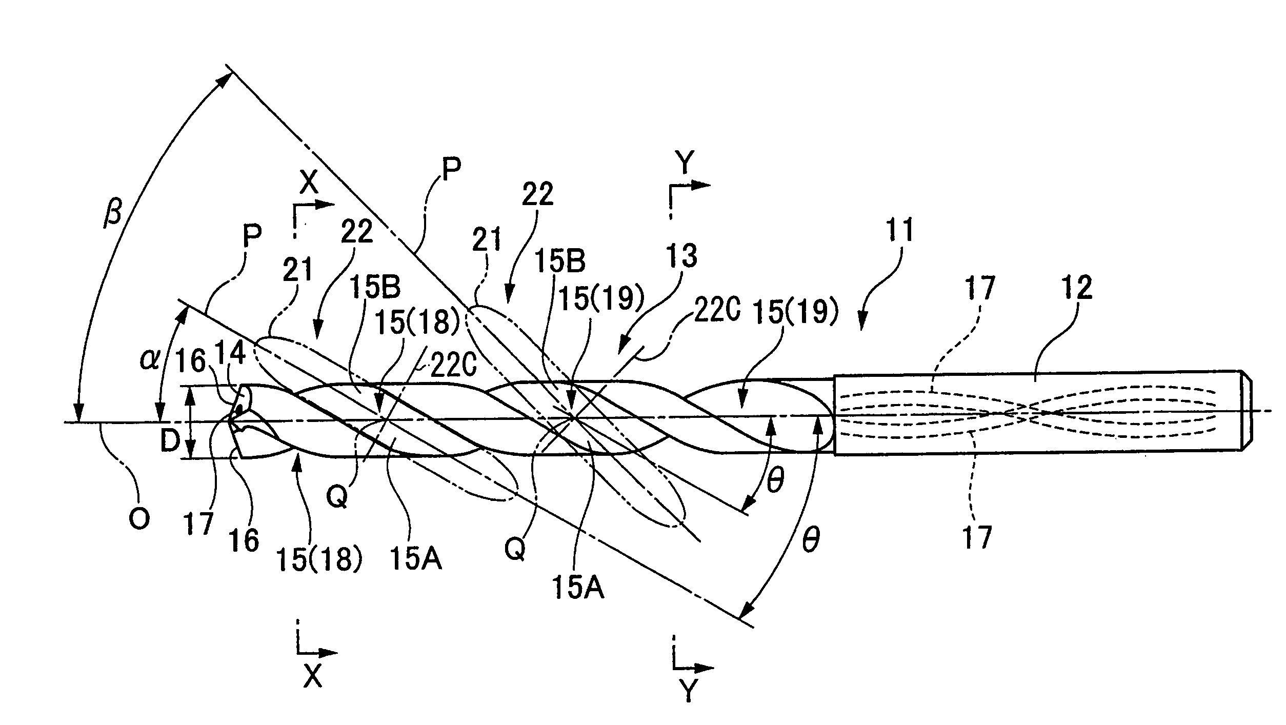
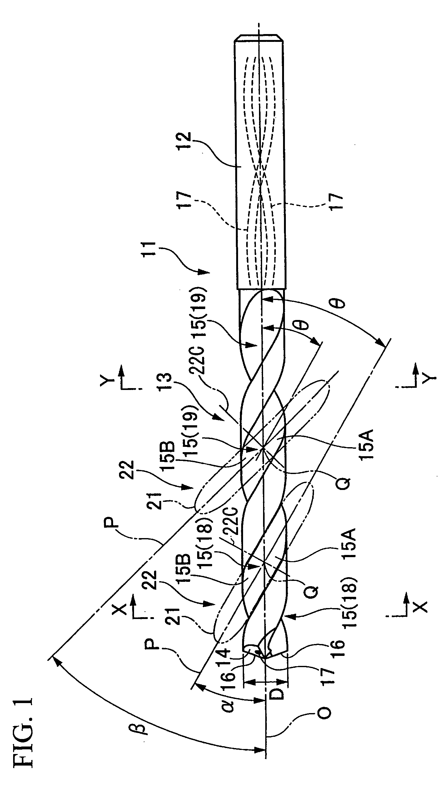
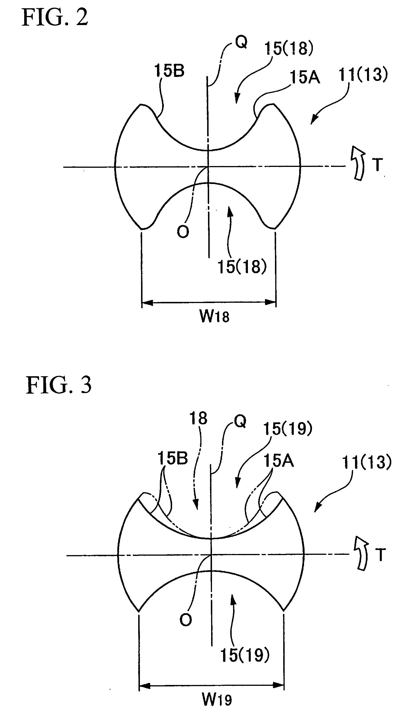
However, since b

Method used


Image

  • Drill and production method thereof
  • Drill and production method thereof
  • Drill and production method thereof

Examples


Embodiment Construction

[0150] A drilling test was conducted using a double margin type drill based on the embodiment shown in FIGS. 11 through 17 as an example of the present invention and a double margin type drill of the prior art as an example of the prior art for the purpose of explaining the effects of the drill shown in FIGS. 11 through 17. Those results are shown in FIG. 18.

[0151] In the example of the present invention, in contrast to the inner wall surface roughness of the entrance section and exit section of a machined hole being satisfactorily maintained at a low level, in the example of the prior art, the inner wall surface roughness of the entrance and exit sections of a machined hole were found to become worse.

[0152] FIGS. 19 through 21 show still another embodiment of the drill of the present invention.

[0153] In the drill of the present embodiment, drill body 201 is composed of a member formed by a hard material such as cemented carbide and is roughly in the shape of a cylindrical column ce...


PUM

PropertyMeasurementUnit
Angleaaaaaaaaaa
Angleaaaaaaaaaa
Diameteraaaaaaaaaa

Abstract

In a drill in which a chip discharge groove twisted in the shape of a spiral relative to an axis is formed in the outer periphery of the tip section of a roughly cylindrical drill body that rotates around the axis, and a cutting edge is formed on the intersecting ridgeline between a wall surface facing in the direction of drill rotation of this chip discharge groove and a tip flank of the drill body, together with the section on the tip side of the chip discharge groove continuous with the cutting edge being a narrowed width section in which the helix angle relative to the axis and groove width are constant, a wide width section is formed in the chip discharge groove farther towards the rear end than this narrow width section, in which the helix angle is equal to the narrow width section and in which the groove width is widened relative to the narrow width section in the direction of drill rotation and towards the rear in the direction of drill rotation and has a constant width.

Description

[0001] 1. Field of the Invention[0002] The present invention relates to a drill, in which a spiral-shaped chip discharge groove is formed in the outer periphery of the tip section of the drill body, and a production method thereof. In addition, the present invention relates to a drill used for hole drilling in order to form a machined hole at a high level of hole positioning accuracy in a drilled material, and for example, relates to a drill for forming a deep machined hole in a metal material.[0003] 2. Background Art[0004] As shown in FIG. 22 through FIG. 24, a known example of a drill (solid drill) in which a spiral-shaped chip discharge groove is formed in the outer periphery of the end section of the drill body is a so-called two-flute twist drill in which a pair of chip discharge grooves 2, which twist to the rear in the direction of rotation of the drill around an axis O towards the rear end from the tip flank of the drill body, are formed symmetrically in the outer periphery ...

Claims


Application Information

Patent Timeline
IPC IPC(8): B23B51/02B23B51/00B23B51/06B24B19/04
CPCB23B51/02Y10T408/78B23B2224/24B23B2224/28B23B2224/32B23B2224/36B23B2228/10B23B2251/04B23B2251/046B23B2251/14B23B2251/18B23B2251/406B23B2251/422B23B2251/443B24B3/24B24B19/04Y10T408/909Y10T408/9097B23B51/06B23B51/063
Inventor MABUCHI, MASAYUKIYANAGIDA, KAZUYASUZUKI, KATSUYUKITAKIGUCHI, SYOJI
Owner MITSUBISHI MATERIALS CORP
Why Eureka
Try Eureka