
Radiographic-image recording medium containing shock-resistant member

a technology of radio-image and recording medium, which is applied in the direction of material analysis using wave/particle radiation, instruments, television systems, etc., can solve the problems of glass substrates also breaking easily upon impact, a-se films having such a thickness are susceptible to damage, and wavelength conversion layers per se are very susceptible to damag

Active Publication Date: 2004-06-03
FUJIFILM CORP +1
View PDF12 Cites 9 Cited by
  • Summary
  • Abstract
  • Description
  • Claims
  • Application Information

AI Technical Summary

Benefits of technology

[0018] Since the radiographic-image recording medium according to the first aspect of the present invention uses the shock-resistant support which is transparent to the radiation (for use in recording) and the wavelength conversion layer containing an organic binder and a fluorescent material which converts the radiation into the first electromagnetic wave (for use in recording), the radiographic-image recording medium according to the first aspect of the present invention resists breakage even when the radiographic-image recording medium is subjected to shock, e.g., dropped, and the portability of the radiographic-image recording medium is enhanced. In addition, since the thickness of the recording-side photoconductive layer can be increased, it is also possible to make the recording-side photoconductive layer resistant to breaking.
[0043] Preferably, in the radiographic-image recording mediums according to the third and fourth aspects of the present invention, the wavelength conversion layer and the photoelectric conversion layer are bonded together through a viscoelastic material which is transparent to the electromagnetic wave for recording. In this case, flexibility at the interface between the wavelength conversion layer and the photoelectric conversion layer increases. In addition, since the wavelength conversion layer and the photoelectric conversion layer together can be bonded together at normal temperature, hardening of an adhesive is unnecessary. Therefore, it is possible to prevent warpage and the like which are caused by the adhesive hardening.

Problems solved by technology

The thickness of the a-Se film required for satisfactorily detecting applied radiation is as much as about 1,000 micrometers. a-Se films having such a thickness are susceptible to damage when dropped.
However, since the above wavelength conversion layer is produced by vapor deposition of CsI, which forms a needle crystal, the wavelength conversion layer per se is very susceptible to damage.
However, such a glass substrate also breaks easily upon impact, such as that applied when dropped.
In addition, since the wavelength conversion layer and the first electrode layer can be bonded together at normal temperature, hardening of an adhesive is unnecessary.
In addition, since the wavelength conversion layer and the photoelectric conversion layer together can be bonded together at normal temperature, hardening of an adhesive is unnecessary.

Method used


Image

  • Radiographic-image recording medium containing shock-resistant member
  • Radiographic-image recording medium containing shock-resistant member
  • Radiographic-image recording medium containing shock-resistant member

Examples


first embodiment

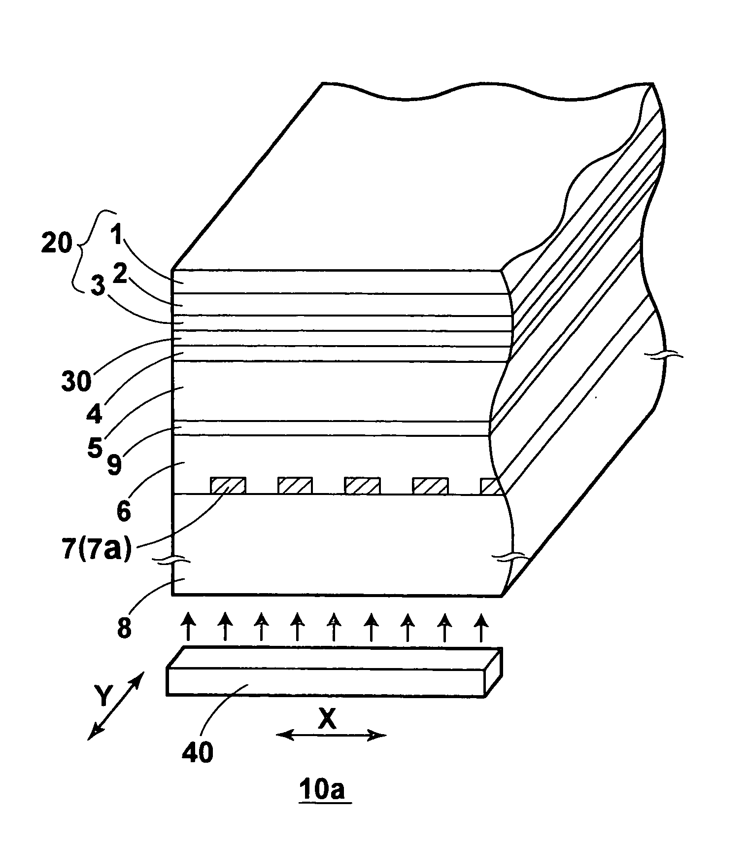
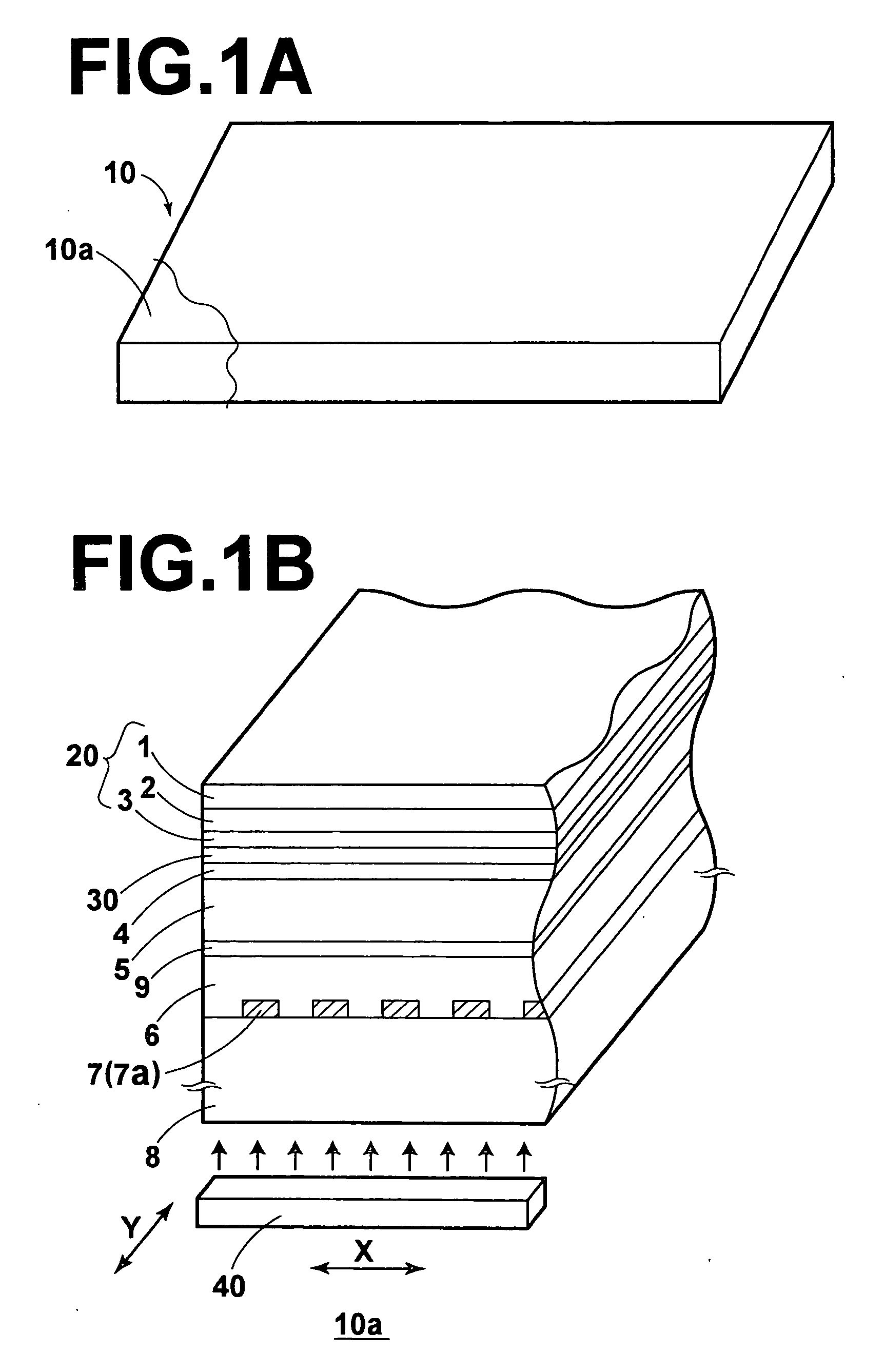
[0055] FIG. 1A is a perspective view of a radiographic-image recording medium according to the first embodiment of the present invention, and FIG. 1B is a magnified perspective view of a cutaway portion 10a of the radiographic-image recording medium 10 of FIG. 1A, where a cross section of the cutaway portion 10a is illustrated in FIG. 1B.

[0056] The radiographic-image recording medium 10 illustrated in FIGS. 1A and 1B comprises a fluorescent layer 20, a first electrode layer 4, a recording-side photoconductive layer 5, a reading-side photoconductive layer 6, a second electrode layer 7, and a substrate 8 are arranged in this order. In addition, a charge storage region 9 is formed at the interface between the recording-side photoconductive layer 5 and the reading-side photoconductive layer 6.

[0057] The fluorescent layer 20 contains a fluorescent material which converts radiation for use in recording, into visible light. The first electrode layer 4 is transparent to the visible light wh...

second embodiment

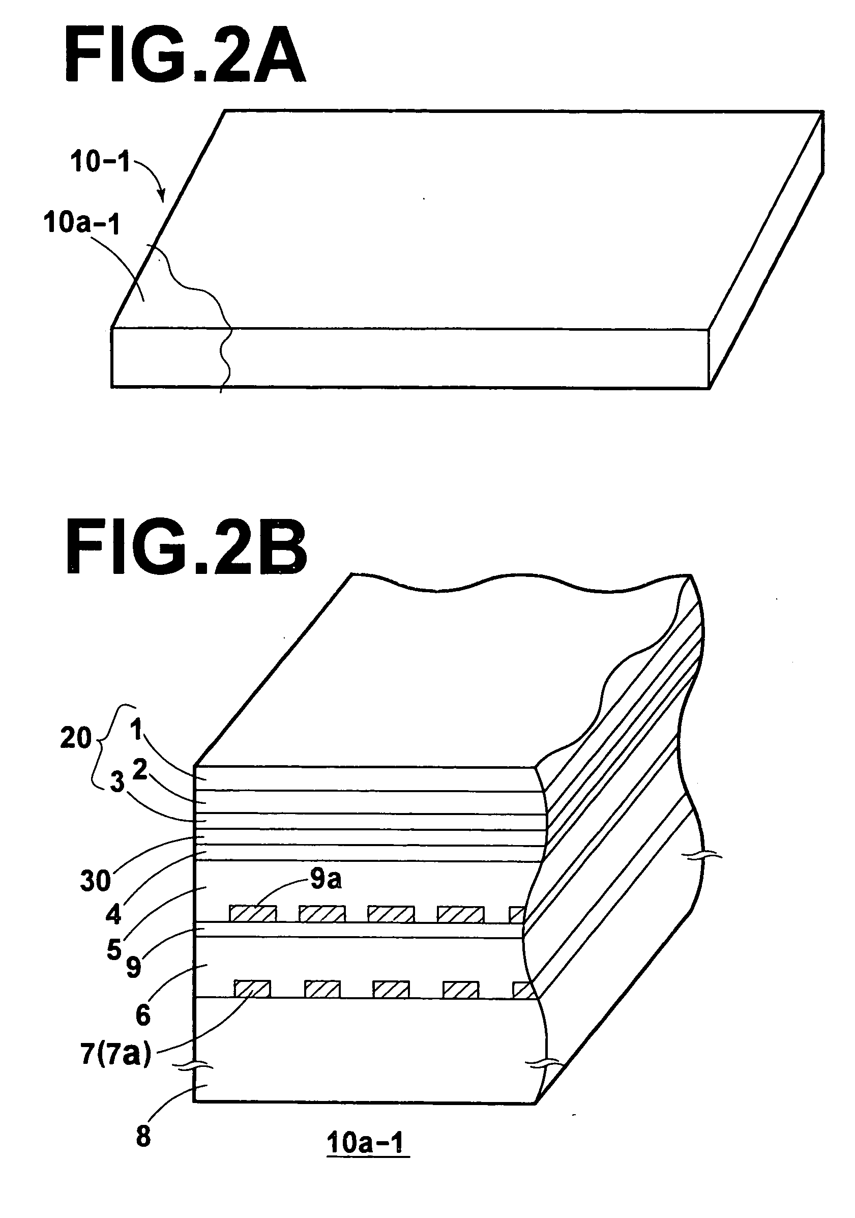
[0073] FIG. 2A is a perspective view of a radiographic-image recording medium according to the second embodiment of the present invention, and FIG. 2B is a magnified perspective view of a cutaway portion 10a-1 of the radiographic-image recording medium 10-1 of FIG. 2A, where a cross section of the cutaway portion 10a-1 is illustrated in FIG. 2B.

[0074] The radiographic-image recording medium 10-1 according to the second embodiment is different from the radiographic-image recording medium 10 according to the first embodiment in that a plurality of microplates 9a are provided at the interface between the recording-side photoconductive layer 5 and the charge storage region 9 so that the plurality of microplates 9a are respectively located opposite to the plurality of elements 7a. For example, the material for the plurality of microplates 9a is formed on the charge storage region 9 by a vacuum evaporation or chemical deposit method. The plurality of microplates 9a can be realized by extr...

third embodiment

[0075] FIG. 3A is a perspective view of a radiographic-image recording medium according to the third embodiment of the present invention, and FIG. 3B is a magnified perspective view of a cutaway portion 10a-2 of the radiographic-image recording medium 10-2 of FIG. 3A, where a cross section of the cutaway portion 10a-2 is illustrated in FIG. 3B.

[0076] The radiographic-image recording medium 10-2 according to the third embodiment is different from the radiographic-image recording medium 10 according to the first embodiment in that the second electrode layer includes the first and second striped electrode arrays, where the first striped electrode array is comprised of a plurality of first elements (first linear electrodes) 17a which are formed with a pitch corresponding to a pixel pitch, and the second striped electrode array is comprised of a plurality of second elements (second linear electrodes) 17b which are arranged alternately with and almost parallel to the plurality of first el...


PUM


Abstract

An image recording medium includes: a support which is transparent to radiation for use in recording, and resistant to shock; a wavelength conversion layer which contains an organic binder and a fluorescent material which converts the radiation into visible light; a first electrode layer which is transparent to the visible light; a recording-side photoconductive layer which exhibits photoconductivity when the recording-side photoconductive layer is exposed to the visible light; a charge storage region which stores electric charges which are generated in the recording-side photoconductive layer in response to exposure to the visible light; a reading-side photoconductive layer which exhibits photoconductivity when the reading-side photoconductive layer is exposed to reading light; and a second electrode layer which is transparent to the reading light.

Description

[0001] 1. Field of the Invention[0002] The present invention relates to a radiographic-image recording medium which records radiographic-image information by storing electric charges generated in response to exposure to radiation.[0003] 2. Description of the Related Art[0004] The following documents (1) and (2) disclose information related to the present invention.[0005] (1) U.S. Pat. No. 6,268,614 issued to the present inventor (Shinji Imai) and corresponding to Japanese Patent Applications Nos. 10-215378 and 10-232824 (which are laid open as Japanese Unexamined Patent Publication No. 2000-105297)[0006] (2) U.S. Pat. No. 6,121,620 corresponding to Japanese Patent Application No. 8-34903 (which is laid open as Japanese Unexamined Patent Publication No. 9-230054)[0007] Conventionally, radiographic-image recording mediums, which record radiographic images by storing in a charge storage region electric charges the amounts of which respectively correspond to doses of radiation such as X...

Claims


Application Information

Patent Timeline
IPC IPC(8): G01T1/20G03C5/17G03G5/02H01L27/14H04N5/32
CPCG03G5/02G03C5/17
Inventor IMAI, SHINJI
Owner FUJIFILM CORP
Learn More