
Arrangement and method to measure cylinder pressure in a combustion engine

a technology of combustion engines and cylinders, which is applied in the direction of engine testing, structural/machine measurement, instruments, etc., can solve the problems of limited service life and reliability of sensors, difficult to arrange appropriate space for fitting such sensors, and solution is only suitable for laboratory use, so as to achieve simple and inexpensive means

Inactive Publication Date: 2004-06-24
SCANIA CV AB
View PDF10 Cites 7 Cited by
  • Summary
  • Abstract
  • Description
  • Claims
  • Application Information

AI Technical Summary

Benefits of technology

[0005] The object of the invention is to make it easier and more certain than previously to obtain reliable information about cylinder pressure in an engine on the basis of analysis of engine vibrations. A further object is to make this possible by simple and inexpensive means.DESCRIPTION OF THE INVENTION
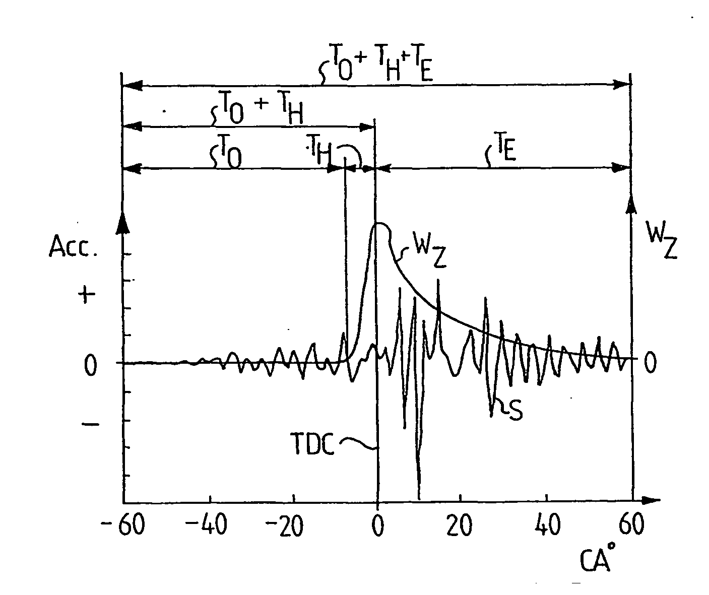
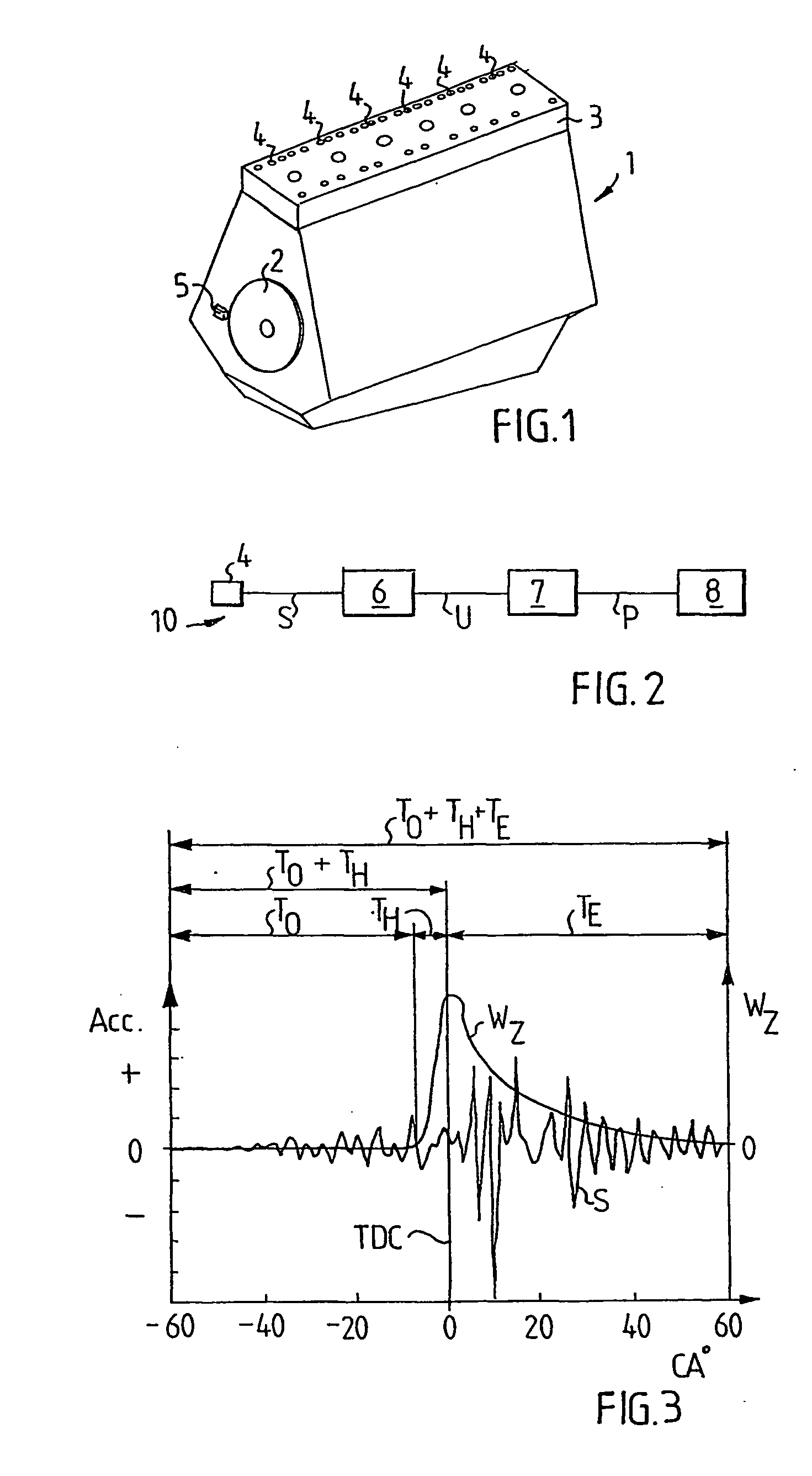
[0007] Using novel and special filtering in the analysis of a vibration signal makes it possible, according to the invention, to analyse reliably the most interesting part of a vibration signal, namely that about the piston's top dead centre position in the cylinder. The novel type of filtering makes it possible to extract a stable vibration signal which, after conversion to pressure signal, can provide reliable pressure determinations usable for determining the state of the engine.

Problems solved by technology

Determining the pressure in a cylinder can be done by means of a pressure sensor fitted in, for example, the cylinder head, but such a method is complicated and also results in the pressure sensor operating in a very difficult environment which limits its service life and reliability.
There is further difficulty in organising appropriate space for fitting such a sensor.
Such a solution is only suitable for laboratory use.
The fact that engines are of complex construction has made it difficult to achieve good and reliable results in this respect.
The way an original pressure signal propagates in the engine is complicated and gives rise to resonances, harmonics and other phenomena which cause problems in interpreting a vibration signal.
Moreover, such factors as piston tilt, valves and adjacent cylinders may influence the vibration signal and make it difficult to interpret.
Various types of filter have been tried but have not produced satisfactory results.

Method used


Image

  • Arrangement and method to measure cylinder pressure in a combustion engine
  • Arrangement and method to measure cylinder pressure in a combustion engine

Examples


Embodiment Construction

[0006] These objects are achieved partly by means of a method whose features are indicated in patent claim 1 and partly by means of an arrangement whose features are indicated in patent claim 9.

[0007] Using novel and special filtering in the analysis of a vibration signal makes it possible, according to the invention, to analyse reliably the most interesting part of a vibration signal, namely that about the piston's top dead centre position in the cylinder. The novel type of filtering makes it possible to extract a stable vibration signal which, after conversion to pressure signal, can provide reliable pressure determinations usable for determining the state of the engine.

[0008] Further advantages and features of the invention are indicated in the ensuing description and patent claims.

[0009] The invention is explained in more detail below with reference to an embodiment depicted in the attached drawings.

DESCRIPTION OF DRAWINGS

[0010] FIG. 1 depicts schematically an engine provided wi...


PUM


Abstract

The pressure in a cylinder of a combustion engine is determined on the basis of vibrations in the engine which are generated during movement of the piston. A vibration signal (S) from a vibration sensor (4) situated on a cylinder is filtered in the region about the piston's top dead centre position, at the transition from compression to expansion, in a special filter (6) in which a half Hanning filter acts upon the vibration signal after the piston's top dead centre position. The filtered signal (U) is thereafter converted to a pressure signal (P) on the basis of an established relationship between vibration and pressure. The half Hanning filter has a significantly shorter time window (TH) than the exponential filter. The novel filter (6) cleans the vibration signal in an advantageous manner and makes more reliable pressure determination possible.

Description

[0001] The invention relates partly to a method for determining the pressure in a cylinder of a combustion engine, according to the preamble to patent claim 1, and partly to an arrangement for determining the pressure in a cylinder of a combustion engine, according to the preamble to patent claim 9.STATE OF THE ART[0002] In a combustion engine it is possible for cylinder pressure to be used for obtaining important information about the combustion process in the engine, but also for ascertaining the condition of the engine. Information about cylinder pressure can therefore be used to monitor the engine and detect any malfunctions.[0003] Determining the pressure in a cylinder can be done by means of a pressure sensor fitted in, for example, the cylinder head, but such a method is complicated and also results in the pressure sensor operating in a very difficult environment which limits its service life and reliability. There is further difficulty in organising appropriate space for fit...

Claims


Application Information

Patent Timeline
IPC IPC(8): G01M15/08G01L23/22
CPCG01M15/08
Inventor GLOWCZEWSKI, MANFRED KLOPOTEK VONVILLARROEL, GORVER ZURITA
Owner SCANIA CV AB
Learn More