
Method of fabricating color filter in display device

a color filter and display device technology, applied in the field of display devices, can solve the problems of increasing the overall fabrication cost of forming the layer containing the color filter, and the use of expensive photo masks

Active Publication Date: 2004-07-01
LG DISPLAY CO LTD
View PDF16 Cites 38 Cited by
  • Summary
  • Abstract
  • Description
  • Claims
  • Application Information

AI Technical Summary

Problems solved by technology

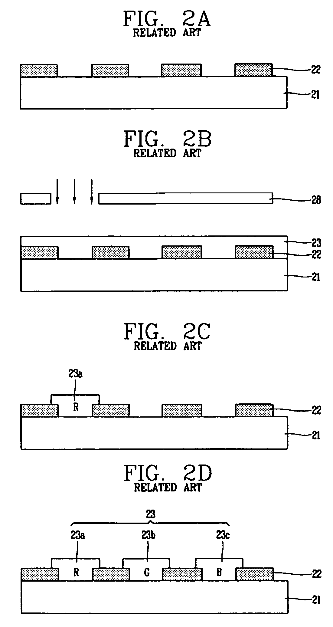
However, in the fabrication method used to form the color filters according to the related art, not only are expensive photo masks used, but in addition, the photolithographic processes, which include the color filter coating, exposure, and development, are repeatedly performed to create the color filter.
The expense of the photo masks as well as the time and costs associated with multiple fabrication steps increase the overall fabrication costs in forming the layer containing the color filters.

Method used


Image

  • Method of fabricating color filter in display device
  • Method of fabricating color filter in display device
  • Method of fabricating color filter in display device

Examples


Embodiment Construction

[0032] Reference will now be made in detail to the embodiments of the present invention, examples of which are illustrated in the accompanying drawings.

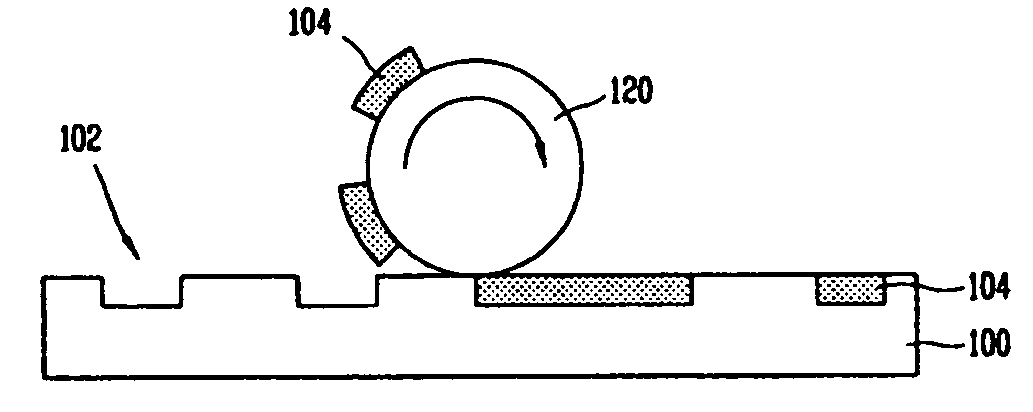
[0033] FIGS. 3A, 3B, and 3C are views illustrating a pattern forming method according to a printing method, in particular, according to a gravure offset printing method.

[0034] First, as shown in FIG. 3A, a groove 102 is formed at one or more positions on a concave plate or clich 100 corresponding to a pattern which will be formed on a substrate, and ink 104 is filled in the groove 102. The filling of the ink 104 into the groove 102 of the clich 100 is performed by applying ink 104 to the clich 100 and the removing a portion of the ink 104 by scraping off the excess / unwanted ink with a blade 108 that contacts the substrate 100. More specifically, excess ink 104 that is filled in the groove 102 and ink 104 remaining on the surface of the clich 100 outside of the grooves 102 is removed by moving the blade 108 along the clich 100, perhap...


PUM


Abstract

A method of fabricating a color filter in a liquid crystal display device includes providing a plurality of clichés in which grooves are formed, filling color inks and a black resin in the grooves of the clichés, applying the color inks in the clichés onto a substrate to form a color filter, and applying a black resin in one of the clichés onto the color filter. The color inks and black resin are transferred to the clichés from an ink supply container via an ink supplying roller and from the clichés to the substrate via a printing roller.

Description

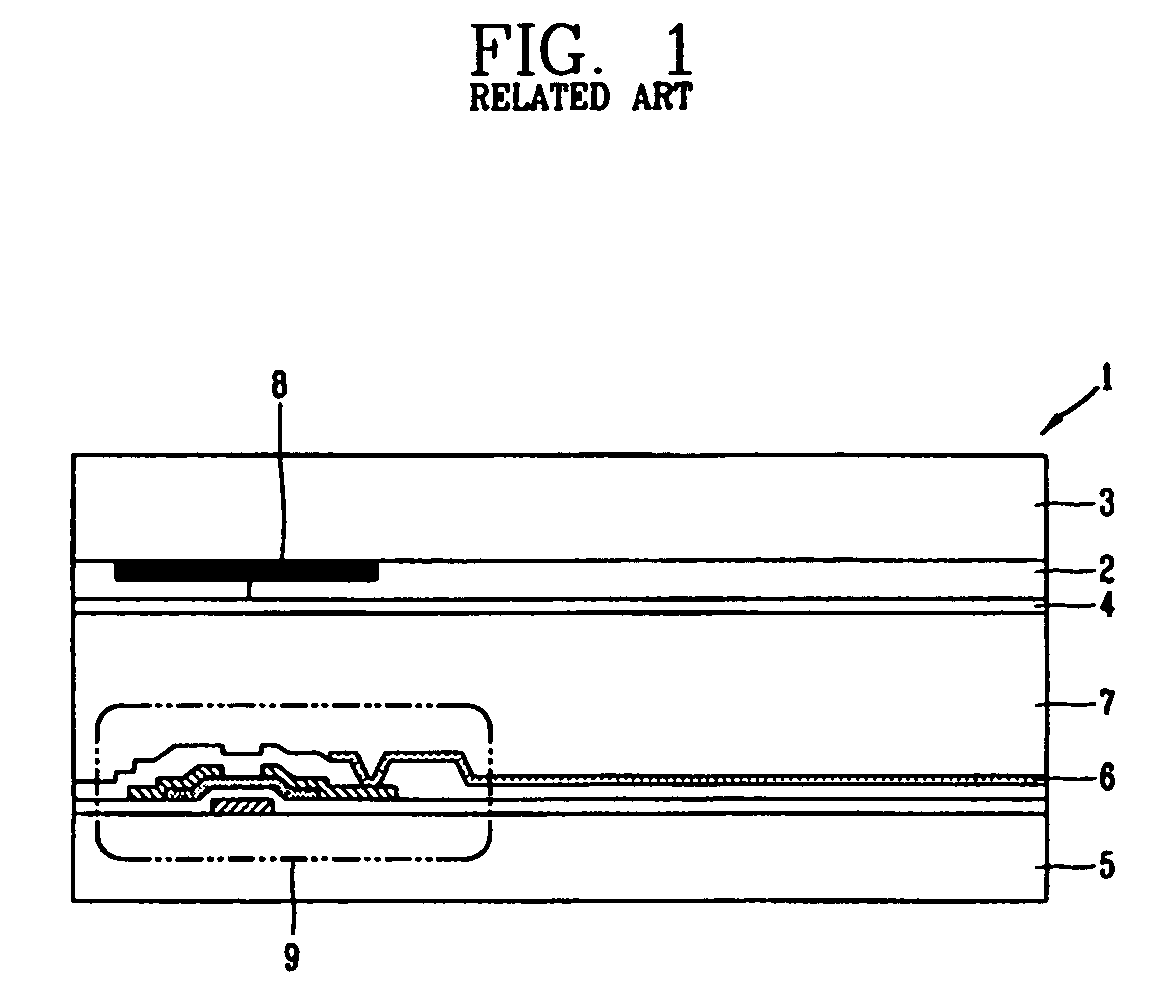
[0001] 1. Field of the Invention[0002] The present invention relates to a display device, and particularly, to a simplified method of fabrication a color filter in a liquid crystal display device having a reduced fabrication cost.[0003] 2. Description of the Related Art[0004] The ongoing development of various portable electric devices such as mobile phones, PDAs, notebook computers, etc. requires concomitant development of thin and small flat panel display devices. Liquid crystal displays (LCD), plasma display panels (PDP), field emission displays (FED), and vacuum fluorescent displays (VFD), for example have all been actively researched for use as the flat panel display, however, the LCD is generally used due to its advanced mass production technology, the easy of driving the devices, and realization of high image quality.[0005] FIG. 1 is a view showing a cross-section of a general liquid crystal display device. As shown therein, the liquid crystal display device 1 comprises a fir...

Claims


Application Information

Patent Timeline
IPC IPC(8): G02F1/1335B41F9/01B41M1/10B41M3/00B41M7/00G02B5/20
CPCB41M1/10B41M3/003B41M7/0072B41M7/009G02F1/133516B41M7/0081G02B5/201G02F1/1335
Inventor YOO, HONG-SUKBAEK, MYOUNG-KEE
Owner LG DISPLAY CO LTD
Learn More