Shower head gas injection apparatus with secondary high pressure pulsed gas injection

a gas injection apparatus and plasma technology, applied in the field of plasma processing, can solve the problems of reducing the size of the orifice, affecting the processing efficiency of plasma processing chambers, and reducing the number of injection orifices

Inactive Publication Date: 2004-07-01
TOKYO ELECTRON LTD
View PDF14 Cites 48 Cited by
  • Summary
  • Abstract
  • Description
  • Claims
  • Application Information

AI Technical Summary

Problems solved by technology

Feed gas distribution systems of known plasma processors that are fixed and have only low pressure injection with respect to the plasma processing chambers have drawbacks.
In order to increase the total pressure for gas injection, one must significantly increase the mass flow rate, reduce the number of injection orifices and / or decrease the orifice size; any of which are generally impractical in conventional systems.
Another drawback of known feed gas distribution systems is that the injection systems are not designed with nozzle orifice geometries suitable to constrain the rate of gas expansion into the low pressure vacuum environment.
Yet another drawback of known feed gas distribution systems is the inadequate continuous high mass flow rate (which is necessary to achieve high injection total pressures).
At present, state-of-the-art vacuum pumping technology is inadequate to produce a pumping speed at the processing region sufficient to accommodate the necessary high throughputs at low pressure for high pressure injection.

Method used


Image

  • Shower head gas injection apparatus with secondary high pressure pulsed gas injection
  • Shower head gas injection apparatus with secondary high pressure pulsed gas injection
  • Shower head gas injection apparatus with secondary high pressure pulsed gas injection

Examples


Embodiment Construction

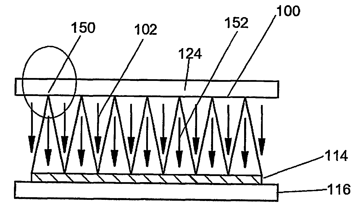
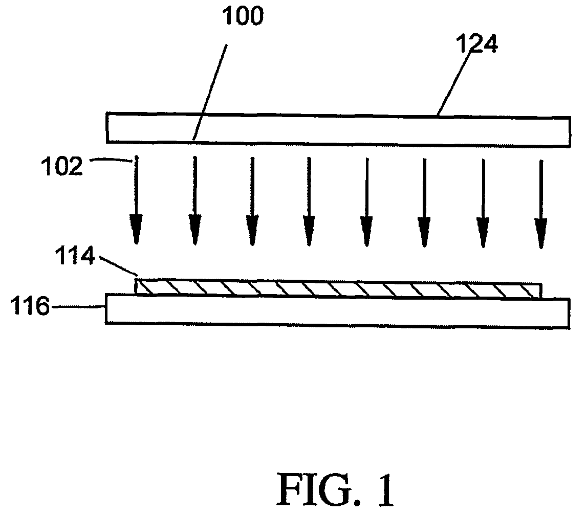
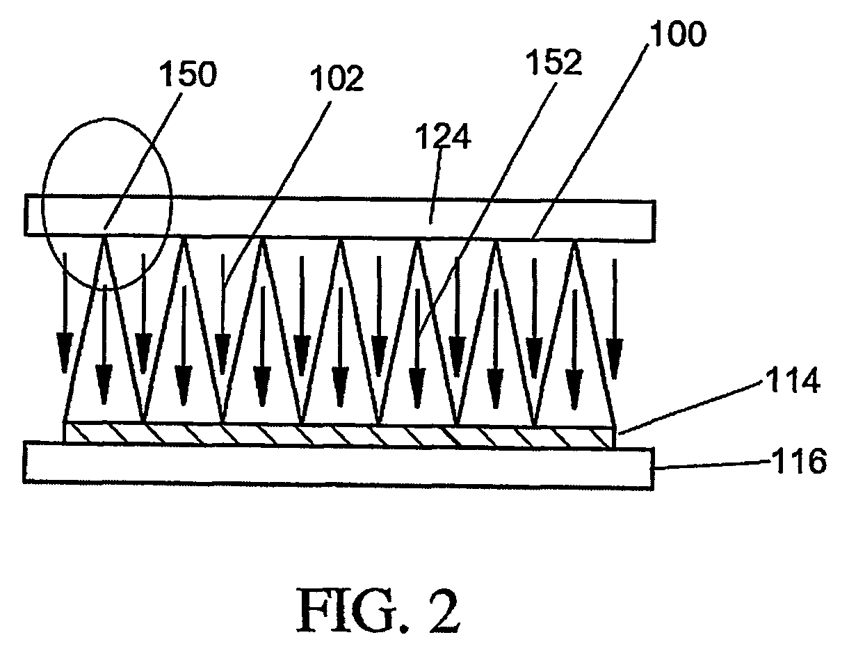
[0023] Referring now to the drawings, in which like reference numerals designate identical or corresponding parts throughout the several views; FIG. 2 illustrates a continuous flow 102 from an array of shower head orifices 100 within an upper electrode 124 toward a substrate 114 on a lower electrode 116. In the preferred embodiment, pulsed injection orifices or nozzles 150 are interlaced within the array of continuous flow shower head orifices 100 (e.g., in a 1:2 ratio). During periods when gas is flowing through only the continuous flow shower head orifices 100, the stationary (or steady-state) pressure field exhibits only spatial gradients which includes primarily radial gradients in its magnitude across the substrate 114. This is due in part to the close spacing of the upper 124 and the lower 116 electrodes. Pulsing the gas through pulsed gas injection orifices / nozzles, in addition to continuously flowing gas through the shower head orifices 100, leads to a non-stationary pressur...


PUM

PropertyMeasurementUnit
diameteraaaaaaaaaa
pressureaaaaaaaaaa
pressuresaaaaaaaaaa

Abstract

A plasma-processing chamber including pulsed gas injection orifices/nozzles utilized in combination with continous flow shower head injection orifices is described. The continous flow shower head injection orifices introduce a continous flow of gas while the pulsed gas injection orifices/nozzles cyclically inject a high-pressure gas into the chamber. In one embodiment, a central computer may monitor and control pressure measurement devices and utilize the measurements to adjust processing parameters (e.g. pulse duration, pulse repetition rate, and the pulse mass flow rate of processing gases).

Description

[0001] 1. Field of the Invention[0002] The present invention generally relates to plasma processing of substrates (e.g., semiconductor wafers or LCD panels) and more particularly, to a method of and an apparatus for pulsed gas injection within a plasma process chamber.DISCUSSION OF THE BACKGROUND[0003] A number of steps in the manufacture of semiconductor wafers may use plasma processing. For instance, resist-stripping, etching, depositing, and passivating, may use plasma processing to produce integrated circuits (hereinafter "ICs") on a substrate. Because the features of the ICs are so small, a uniform plasma density is required for satisfactory resolution thereof. A high plasma density is also necessary in order to maintain process throughputs within a commercially viable range.[0004] Typically, plasmas are established in low-pressure gas environments by causing electrons to collide with individual atoms or molecules, thereby producing additional free electrons and ions. In order ...

Claims


Application Information

Patent Timeline
Patent Type & Authority Applications(United States)
IPC IPC(8): C23C16/44C23C16/455C23C16/509H01J37/32
CPCC23C16/455C23C16/45557H01J37/3244C23C16/5096C23C16/45565
Inventor STRANG, ERIC J.
Owner TOKYO ELECTRON LTD
Why Eureka
Try Eureka