Breast pump system

a pump system and breast milk technology, applied in the field of breast milk apparatus and methods, can solve the problems of inefficient breast milk expression, elongation and distention of the nipple in an axial direction, and the only vacuum source applied in the system,

Inactive Publication Date: 2004-07-01
PLAYTEX PROD INC
View PDF99 Cites 106 Cited by
  • Summary
  • Abstract
  • Description
  • Claims
  • Application Information

AI Technical Summary

Problems solved by technology

Such systems suffer from the drawback of applying only a vacuum source as negative pressure to the breast to induce the expression of breast milk.
Moreover, such conventional systems suffer from the drawback of applying the negative pressure or force axially to the nipple, resulting in elongation and distention of the nipple in an axial direction that is both uncomfortable and inefficient for the expression of breast milk.

Method used


Image

  • Breast pump system
  • Breast pump system
  • Breast pump system

Examples


Embodiment Construction

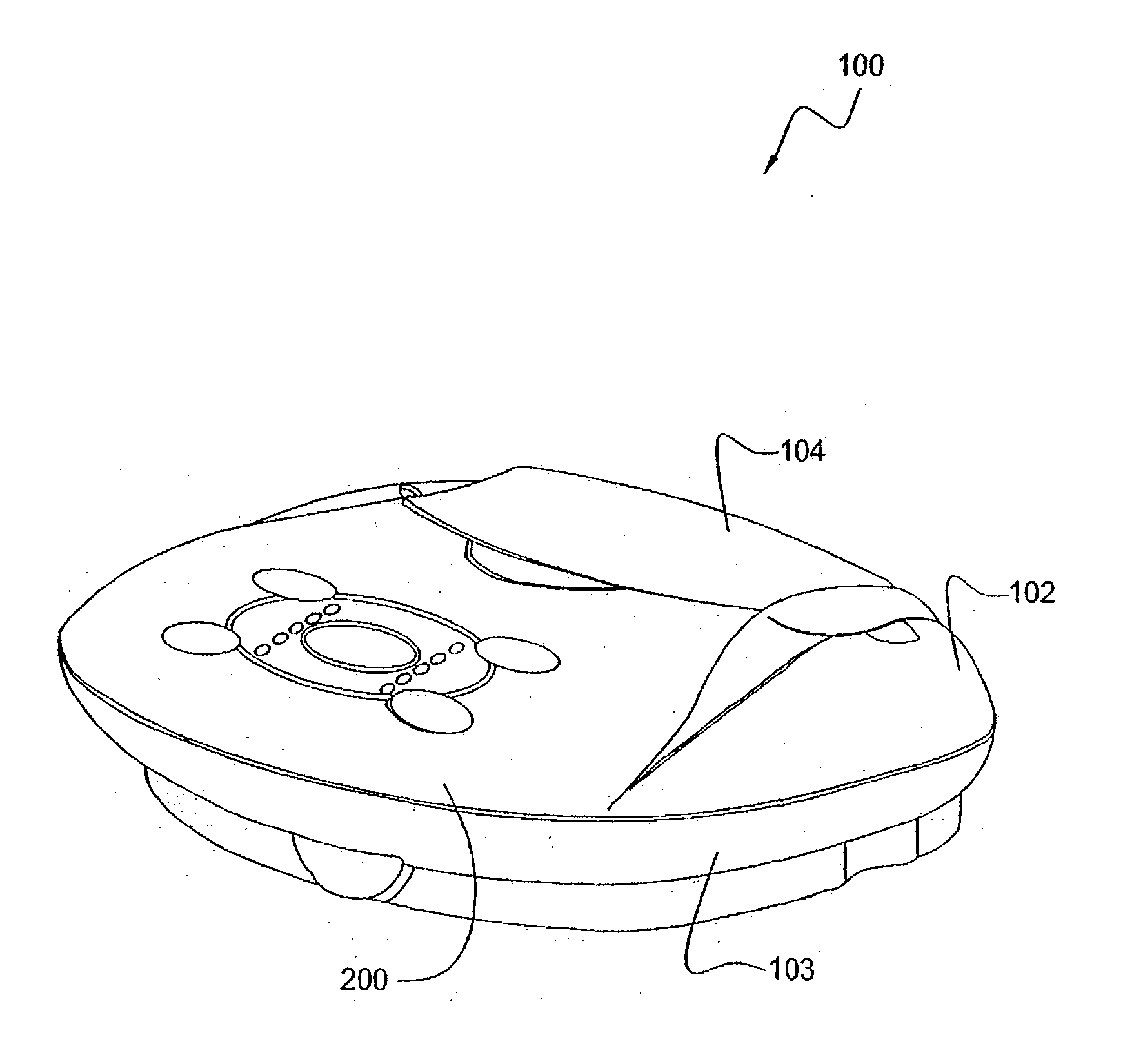
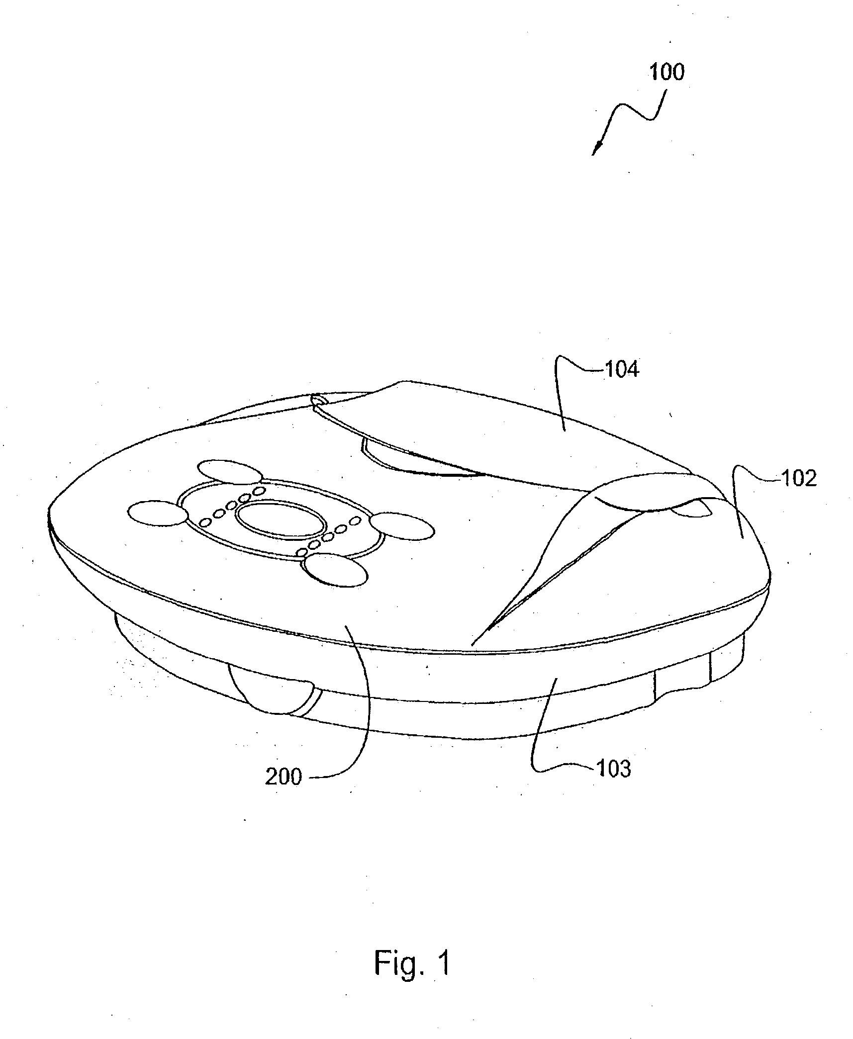
[0078] Referring to the drawings and, in particular, FIGS. 1 and 2, there is shown a breast pump of the present invention generally represented by reference numeral 100. Breast pump 100, along with breast cup 400 shown in FIG. 11, form the major components of the breast pump system of the present invention. Breast pump 100 has a top housing 102 and a bottom housing 103 that are adapted to form an assembled unit.

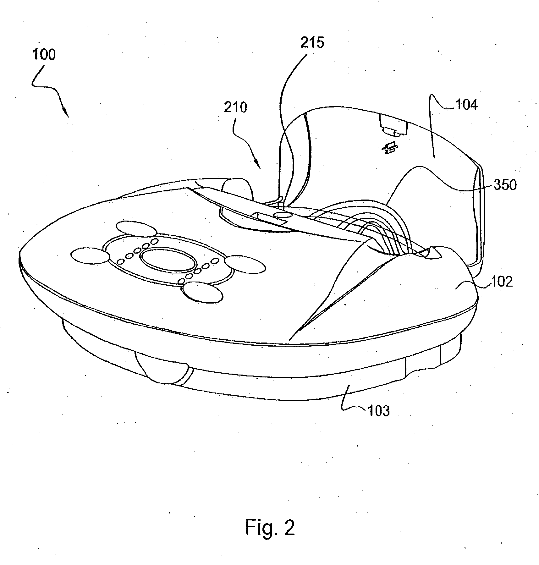
[0079] Referring to FIGS. 1 through 3, top housing 102 has a substantially ellipsoidal shape with a flat front face 200 and a storage compartment 210 having a compartment door 104. Preferably, door 104 is hingedly connected to top housing 102 to form a selectively sealable storage compartment 210 for storing air tubing or conduit 350 that connects breast pump 100 to the other components of the system, which will be discussed later in greater detail.

[0080] Face 200 can receive a button pad 105 having an LED cover 106. Pad 105 is used by the consumer to control breast pump 100....


PUM


Abstract

A breast pump system for obtaining breast milk is provided. The system sealingly separates the air flow from the breast milk and uses a single air tube for both positive pressure and negative pressure to be applied to a woman's breast. The breast pump can have a piston/cylinder device for generating pressure that allows a user to control suction and cycle time.

Description

[0001] This application is a continuation-in-part of copending U.S. application Ser. No. 10 / 331,183, filed Dec. 27, 2002, the disclosure of which is incorporated by reference herein in its entirety. This application is also a continuation-in-part of copending U.S. application Ser. No. 10 / 453,261, filed Jun. 3, 2003, the disclosure of which is also incorporated by reference herein in its entirety.[0002] 1. Field of the Invention[0003] The present invention relates to apparatus and methods for obtaining breast milk. More particularly, the present invention relates to a breast pump system that can apply a positive pressure or a negative pressure to a breast to express breast milk.[0004] 2. Description of the Related Art[0005] Breast pump systems for obtaining breast milk, both manually and automatically, are known in the art. Conventional systems use a vacuum source to generate a negative pressure or vacuum that is transmitted through tubing to a breast hood or cup that is placed on th...

Claims


Application Information

Patent Timeline
Patent Type & Authority Applications(United States)
IPC IPC(8): A45C3/06A45C5/06A45C11/00A45C13/02A45C15/00A61MA61M1/00A61M1/06
CPCA45C3/06A45C5/06A45C11/00A45C13/02A61M1/066A61M1/0037A61M1/06A61M1/0068A61M1/064A45C15/00A61M1/75A61M1/81A61M1/0697A61M1/06935
Inventor RENZ, CHARLES J.ROBSON, DAVIDWO, MARCOKAMPF, CHRISTOPHERPETRIE, AIDANPEREIRA, MICHAEL
Owner PLAYTEX PROD INC
Why Eureka
Try Eureka