Method of manufacturing an optical fiber ribbon, and an optical fiber ribbon

a manufacturing method and ribbon technology, applied in the direction of cable/conductor manufacturing, instruments, electrical equipment, etc., can solve the problems of low productivity of the manufacturing method of optical fiber ribbon, achieve simple implementation, reduce time and/or cost of manufacturing the ribbon, and improve the effect of product quality

Inactive Publication Date: 2004-07-08
NEXANS
View PDF0 Cites 4 Cited by
  • Summary
  • Abstract
  • Description
  • Claims
  • Application Information

AI Technical Summary

Benefits of technology

[0014] An object of the invention is to develop a method of manufacturing an optical fiber ribbon made up of a plurality of subsets provided with respective casings that are disposed in a common plane, that are separable, and that are connected together by a "link" matrix, said method presenting satisfactory productivity (reducing the time and / or the cost of manufacturing the ribbon) and preferably being simple to implement.

Problems solved by technology

The productivity of that method of manufacturing an optical fiber ribbon is low because the method requires multiple operations of changing machine and putting work into place.

Method used


Image

  • Method of manufacturing an optical fiber ribbon, and an optical fiber ribbon
  • Method of manufacturing an optical fiber ribbon, and an optical fiber ribbon
  • Method of manufacturing an optical fiber ribbon, and an optical fiber ribbon

Examples


Embodiment Construction

[0049] Elements that are common to the various embodiments of the invention are designated by the same references.

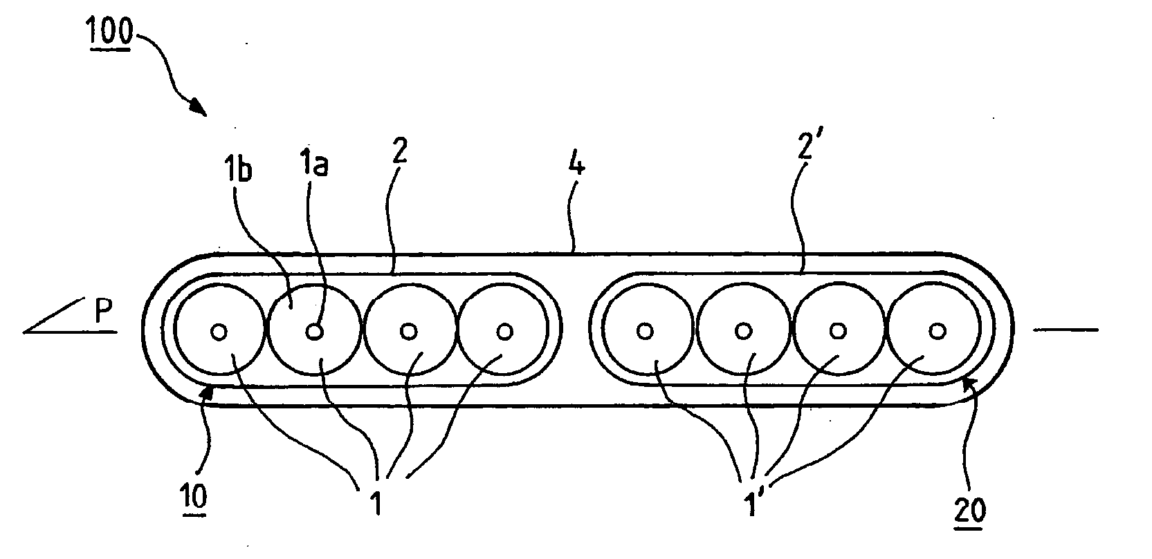
[0050] FIG. 1 is a diagram of an optical fiber ribbon 100 in a first preferred embodiment of the invention.

[0051] By way of example, the optical fiber ribbon 100 comprises two subsets of optical fibers 10, 20 disposed in a common plane P and separable from each other.

[0052] Each subset 10, 20 comprises a group 1, 1', e.g. four optical fibers disposed in said plane P.

[0053] Each optical fiber is conventionally constituted by a core 1a surrounded by optionally-colored covering 1b for identifying each fiber.

[0054] Each group of four optical fibers 1, 1' is covered in a respective first matrix 2, 2' in the form of a first casing, preferably obtained by a radical process, by irradiating a first liquid resin that can be set by UV type radiation. By way of example, the first resin, referred to as "resin A.sub.1", is based on acrylate and corresponds, for example, to the product...


PUM

PropertyMeasurementUnit
thicknessaaaaaaaaaa
mechanical strengthaaaaaaaaaa
timeaaaaaaaaaa

Abstract

The present invention relates to a method of manufacturing an optical fiber ribbon comprising the following steps: arranging N groups of optical fibers so that the fibers in any one group are disposed in the same plane, applying a first layer of a first liquid resin settable under the action of UV type radiation onto each group of optical fibers to form first casings, applying a second layer of a second liquid resin settable under the action of UV type radiation disposed to link together the adjacent first casings, and applying a single irradiation step to the second layer and the first layers using UV type radiation in order to form the first matrices and to form the "link" second matrix.

Description

[0001] This application is related to and claims the benefit of priority from French Patent Application No. 02 14369, filed on Nov. 18, 2002, the entirety of which is incorporated herein by reference.[0002] The present invention relates to the field of optical fiber telecommunications cables, and more precisely it relates both to a method of manufacturing an optical fiber ribbon and to an optical fiber ribbon.[0003] In conventional manner, optical fiber ribbons are used in telecommunication cables for conveying information optically.[0004] Document EP 0 950 908 discloses an optical fiber ribbon comprising, for example, two subsets disposed in a common plane, the subsets being connected to each other and being separable so as to make them easier to install respectively in optical systems.[0005] More precisely, each subset comprises a group of optical fibers arranged in a common plane, said group being coated in a first matrix forming a first casing and obtained by irradiating a first...

Claims


Application Information

Patent Timeline
Patent Type & Authority Applications(United States)
IPC IPC(8): C03C25/10C03C25/1065G02B6/44H01B11/00H01B13/00
CPCC03C25/1065G02B6/448G02B6/4404G02B6/44
Inventor FOURNIER, JEROMEPINTO, OLIVIERELISSON, PETERGUNNARSSON, MAGNUSLANNED, MATS
Owner NEXANS
Why Eureka
Try Eureka