Sensor device and wiper controller

a technology of sensor device and wiper controller, which is applied in the direction of vehicle cleaning, instruments, dynamo-electric converter control, etc., can solve the problems of increased production cost, increased cost, and change in the amount of light received by the light reception device, and achieve high cost-performance, high space efficiency, and high accuracy in raindrop detection.

Active Publication Date: 2007-02-15
DENSO CORP
View PDF11 Cites 6 Cited by
  • Summary
  • Abstract
  • Description
  • Claims
  • Application Information

AI Technical Summary

Benefits of technology

[0009] In view of the above-described and other problems, the present invention provides a raindrop detection device that has high accuracy in raindrop detection and high cost-performance. The present invention also provides a raindrop detection device that has a high space efficiency when it is disposed on a windshield of a vehicle.
[0010] According to an embodiment of the present invention, the raindrop detection device uses one light emitting device and two light reception devices for emitting and receiving a light. The two light reception devices receive the light from respectively different light paths. That is, a first light reception device and a second light reception device are used to receive the light, and the first light reception device receives the light reflected by the windshield, and the second light reception device receives the light that is not reflected by the windshield. In this manner, the first and the second light reception devices receive different amounts of the light emitted from the same light emitting device. Therefore, the ratio of the amounts of the light received by the two light reception devices is temperature independent, because the temperature dependent portion of the amounts of the light received by the light reception devices is cancelled in the course of calculating the ratio, that is, dividing one amount by the other amount both having the same temperature factors. As a result, the raindrop detection device that detects raindrops based on the change in the amount of the light reflected by the windshield is accurate regardless of the temperature of the environment. In addition, the ratio of the amounts of the received light by the first and the second light reception devices can be determined by using only one light emitting device, thereby reducing time and cost for collecting a large amount of data.
[0011] According to one aspect of the present invention, each of the two light reception devices receives the light at respectively different rate against the amount of the light originally emitted by the light emitting device. Therefore, each of the reception rates are temperature independent, because temperature dependent factors in the original amount of the light and in the received amount of the light cancel each other in the reception rate. As a result, the ratio of the two reception rates is also temperature independent, and the raindrop detection device can accurately detect raindrops by calculating the ratio of the reception rates derived from the two light reception devices. In addition, the ratio of the two reception rates of the received light by the first and the second light reception devices can be determined by measuring two amounts of the light emitted by the two light emitting devices, thereby reducing time and cost for data collection.

Problems solved by technology

That is, the amount of the light received by the light reception device changes when a surface of the windshield is wet.
The correlation data collection procedure by sampling outputs of the light reception device is not only time-consuming but leads to an increased cost of production.
In addition, the data storage device for storing a large amount of the correlation data also contributes to the increase of the cost.
Therefore, the utilization of the space in the raindrop detection device in the disclosure is unavoidably restricted.

Method used


Image

  • Sensor device and wiper controller
  • Sensor device and wiper controller
  • Sensor device and wiper controller

Examples


first embodiment

[0045] (First Embodiment)

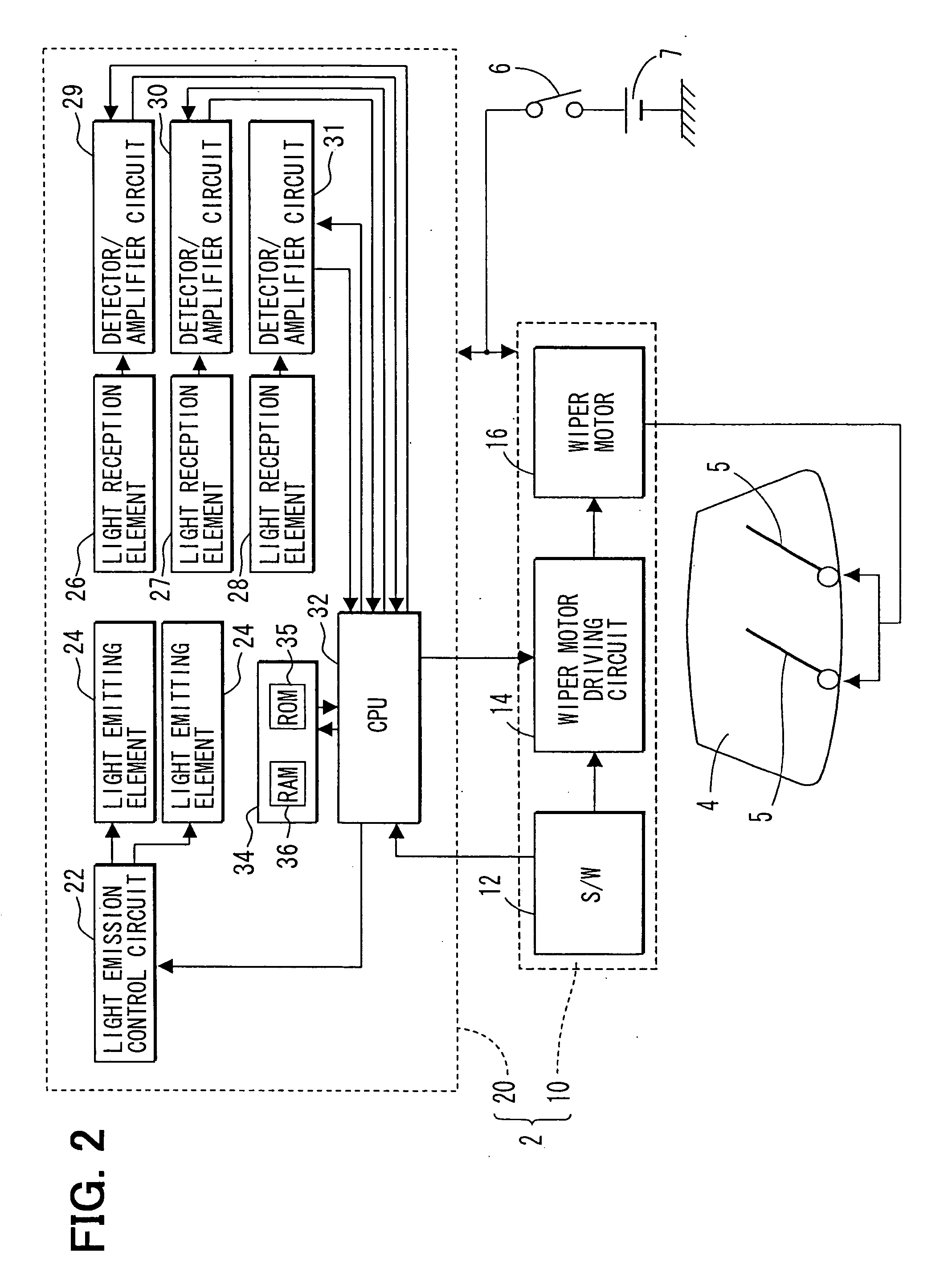
[0046]FIG. 2 shows a block diagram of a wiper controller in the first embodiment of the present invention. The wiper controller 2 controls wipers 5 used in a vehicle for wiping raindrops on a windshield 4.

[0047] The wiper controller 2 includes a wiper driving device 10 and a raindrop detection device 20. Electric power supply is provided from a battery 7 to the wiper driving device 10 and the raindrop detection device 20 through an ignition switch 6.

[0048] The wiper driving device 10 includes a wiper switch 12, a wiper motor driving circuit 14, and a wiper motor 16. The wiper switch 12 is disposed at a position that is close to a driver's seat in the vehicle. The wiper switch 12 has a plurality of control positions of wiping operation such as “auto,”“low,”“middle,”“high,”“stop” and the like. The wiper switch 12 outputs a control position signal that indicates a control position of the switch 12 to the wiper motor driving circuit 14 and a CPU 32 in the rain...

second embodiment

[0086] (Second Embodiment)

[0087] In the present embodiment, the wiper controller processes the regular rain detection in the same way as the initial rain detection as described in the first embodiment. That is, steps S31 to S35 in the flowchart in FIG. 9 are the same as steps S11 to S15 in the flowchart in FIG. 6 in the first embodiment. In this manner, the control process of the wiper controller is simplified without compromising the accuracy of detection.

third embodiment

[0088] (Third Embodiment)

[0089] The regular rain detection of the wiper control process in a third embodiment of the present invention is described with reference to a flowchart in FIG. 10.

[0090] The regular rain detection starts with step S41, which is the same process as step S11 in the initial rain detection.

[0091] In step S42, three fail-safe criteria are examined. That is, the process proceeds to step S43 if at least one of the three criteria is met. In this case, the process is determined as a normal condition. The process proceeds to step S47 if all of the three criteria are met. The process proceeds to step S47 for handling an abnormal condition based on the examination of the three criteria.

[0092] The three criteria for fail-safe are as follows:

[0093] (1) Each of the amounts R1, R2 of the light received by the first and second light reception elements stored in the RAM 36 in step S41 is not 0;

[0094] (2) The amount R3 of the light received by the third light reception e...


PUM

PropertyMeasurementUnit
angleaaaaaaaaaa
angleaaaaaaaaaa
wettingaaaaaaaaaa

Abstract

A sensor device for detecting wetting on a windshield includes a light emission element for emitting a light, a first light reception element for receiving the light in a first light path that includes reflective redirection by the windshield, and a second light reception element for receiving the light in a second light path that does not include reflective redirection by the windshield. The sensor device uses a ratio of the amount of the received light by the first light reception element and the amount of the received light by the second light reception element to determine wetting on the windshield.

Description

CROSS REFERENCE TO RELATED APPLICATION [0001] This application is a divisional of U.S. patent application Ser. No. 11 / 239,121 filed Sep. 30, 2005 which was based on and claims priority from Japanese Patent Application No. 2004-297680 filed on Oct. 12, 2004, the disclosure of which is incorporated herein by reference.FIELD OF THE INVENTION [0002] The present invention generally relates to a raindrop detection device and a wiper controller for controlling a wiping system of a windshield. BACKGROUND OF THE INVENTION [0003] A wiper controller conventionally uses a raindrop detection device for automatically controlling a wiping system that removes raindrops from a windshield of a vehicle. [0004] The raindrop detection device uses a light emitted from a light emitting device and received by a light reception device for detecting moisture on the windshield. Japanese Patent Document JP-A-2001-349961 and U.S. Pat. No. 6,433,501 disclose the raindrop detection device that detects wet conditi...

Claims


Application Information

Patent Timeline
Patent Type & Authority Applications(United States)
IPC IPC(8): G02B6/42G01N21/49
CPCB60S1/0822G01N21/552B60S1/0837
Inventor YOSHIGOE, TAKETOSHIISHIKAWA, JUNICHIMORISHITA, TAIJI
Owner DENSO CORP
Why Eureka
Try Eureka