
Adjustable and reversibly securable terrace stairs

a terrace and adjustable technology, applied in the field of terrace stairs, can solve the problems of unsecured risers, prone to dislocation, and the inside of the riser surface has to be compacted, and achieves the effect of convenient filling and leveling of each step, convenient and quick adjustment, and convenient compacting

Inactive Publication Date: 2004-07-22
KAMBARA GORO
View PDF5 Cites 1 Cited by
  • Summary
  • Abstract
  • Description
  • Claims
  • Application Information

AI Technical Summary

Benefits of technology

0009] Accordingly, several objects and advantages of this invention are:
0010] (a) to provide stairs with risers that are adjustable in location for the incline and curvature of slope;
0011] (b) to provide stairs that have a way to secure the adjustments easily and quickly once the adjustments are made so that the soil can be easily compacted against the

Problems solved by technology

A paramount disadvantage of this prior art methodology is that the soil has to be compacted against the inside of the riser surface.
Since the riser is not secured, it is prone to disposition.
Moreover, unsecured risers may also be subsequently displaced by use, erosion and / or other forces arising from changing climatic conditions.
While compacting of the soil is greatly facilitated, there is a loss of flexibility in that the incline becomes fixed and yaw angle is only adjustable by skewing the next tread against the installed riser, resulting in a less aesthetic frontal appearance.
This however, necessitates delays in that work can progress only at a rate determined by the bonding time.
Moreover, this approach does not allow for correction once adhesion is complete.
This solution too has obvious problems; the treads must have a number of threaded inserts to allow for adjustments, which are not only expensive but also unsightly.
But this approach also creates another problem, namely, the soil has to be contoured to fit the next stair while the next stair is not yet in place--so there is an element of anticipatory fill making and compacting, which is much trial and error and labor intensive.
A collateral disadvantage of this product is due to its shape and bulk.
Shipment and storage require more space than separate steps and risers.
A fundamental disadvantage of all prior art structures is that they do not lend themselves to installation in open unbounded terrain.
When installed in open slope without structures on both sides, rain erodes the soil adjacent to the stairs creating a ditch along both sides.
This can result in unsafe conditions, which are sometimes not obvious to persons using them.

Method used


Image

  • Adjustable and reversibly securable terrace stairs
  • Adjustable and reversibly securable terrace stairs

Examples


Embodiment Construction

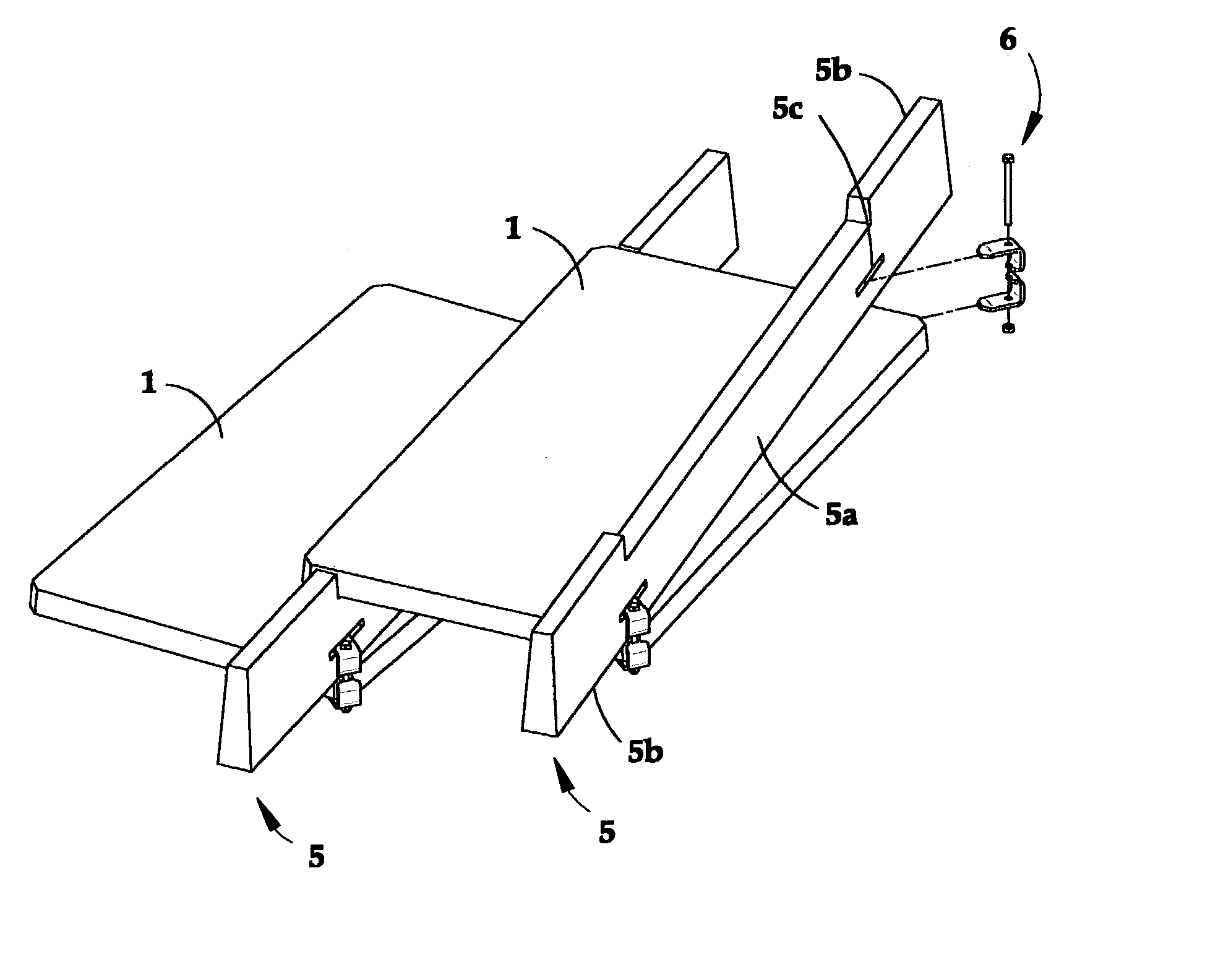
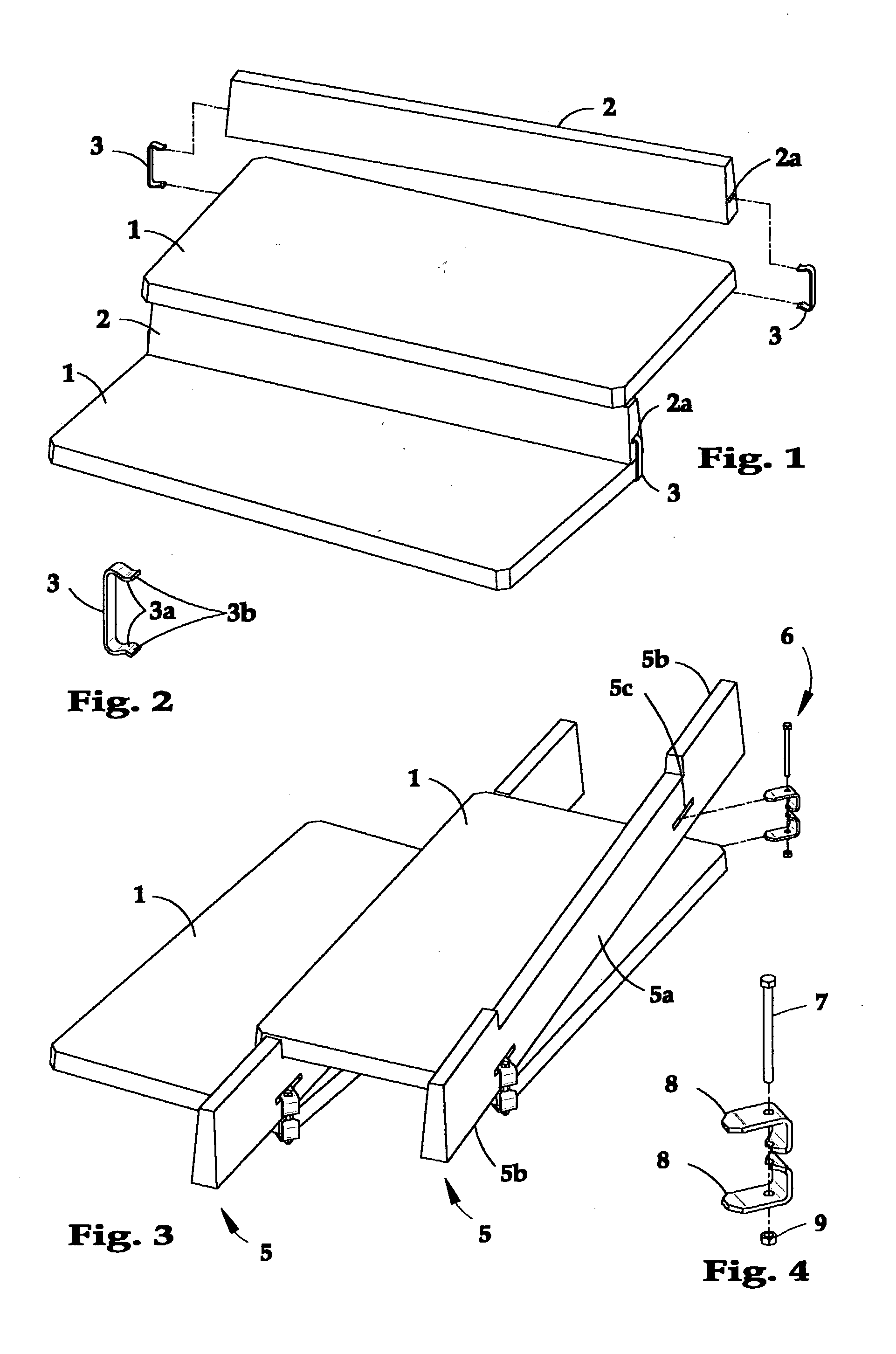
[0036] A preferred embodiment of the invention is illustrated in FIG. 1 with spring clamp 3 enlarged as shown in FIG. 2. The combination has a tread 1, riser 2 and two spring clamps 3. Step 1 and riser 2 are preferably concrete, rock or plastic; spring clamp 3 is preferably metal or plastic with sufficient spring force for having clamping surface 3a and lead-in angle 3b in each leg. Riser 2 has two spring clamp cavities 2a, one at each end. Spring clamp cavity 2a is located such that the jaws of spring clamp 3 will have sufficient tension when spread apart so as to function as a clamp when forcibly positioned over the bottom surface of tread 1 and upward surface of spring clamp cavity 2a. Lead-in angle 3b in each leg of spring clamp 3 eases the installation of it by providing starting slope for the spring. Clamping surfaces 3a would be contacting two surfaces when installed. Riser 2 can thus be clamped to tread 1 in the desired location and yaw angle within the limits of the structu...


PUM


Abstract

Stair elements installed on sloped ground starting bottom up and using a riser reversibly secured with a clamping mechanism. Each riser is attached to a corresponding tread at the time of installation. The manner of fixing the riser to the tread permits the relationship between the two to be adjusted for angle and position.

Description

BACKGROUND--FIELD OF INVENTION[0001] This invention relates to exterior stairs, specifically terraced stairs used for landscaping customarily installed stair by stair in accordance with the topography.BACKGROUND--DESCRIPTION OF PRIOR ART[0002] One of the traditional ways to make terrace stairs on sloped ground is to lay a flat piece of rock or concrete as a starter tread at the bottom of the slope where the stairs begin, and place one or more barrier bricks at far end of the treads to form a riser, The area so formed is then back filled with soil and leveled even with the top of the bricks. The first stair tread is then placed thereon, and the procedure repeated the next step and so on until the stairs reach the desired height.[0003] The method has the advantage that it permits the installer to vary the angle of incline to accommodate the slope within the range bricks can be placed. For example, if the bricks that form the rise height are placed at farthest end of tread, the incline...

Claims


Application Information

Patent Timeline
IPC IPC(8): E04F11/00E04F11/09E04F11/116
CPCE04F11/116E04F11/00
Inventor KAMBARA, GORO
Owner KAMBARA GORO
Learn More