Endoscope system

Inactive Publication Date: 2004-07-22
BAY CITY CAPITAL FUND IV
View PDF14 Cites 47 Cited by
  • Summary
  • Abstract
  • Description
  • Claims
  • Application Information

AI Technical Summary

Benefits of technology

0207] When the special light mode (observation under special light) is designated, an object from which feeble light is returned and which cannot be visualized by a typical CCD can be visualized owing to multiplication of electrons flowing in each CMD in the CCD and automatic gain control. Moreover, the signal-to-noise ratio relative to an image signal and the output voltage level of the image signal are improved. This results in a view image of excellent image quality (high signal-to-noise ratio) and proper brightness.
0208] Information read from the ROM 170 may represent a type of endoscope or the brightness of an image displayed on the monitor 105 (output voltage level provided by the processor 103) instead of the CMD multiplication rates for CCD 109 predefined for the ordinary light mode and special light mode. Otherwise, correction data for a difference in the CCD multiplication rate for the CCD 109 from one pixel location to another may be transmitted to the processor 103.
0209] Two CCDs may be incorporated in the distal part of an endoscope, and the first CCD of the CCDs may be used exclusively for the o

Problems solved by technology

However, when an iris diaphragm is fully opened in order to adjust the amount of irradiated light, if the electronic shutter is activa

Method used


Image

  • Endoscope system
  • Endoscope system
  • Endoscope system

Examples


Example

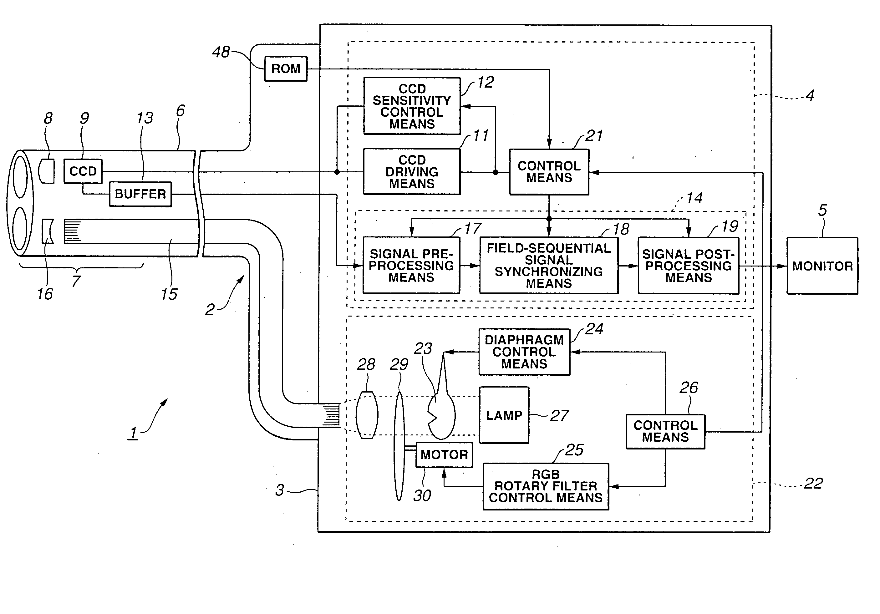
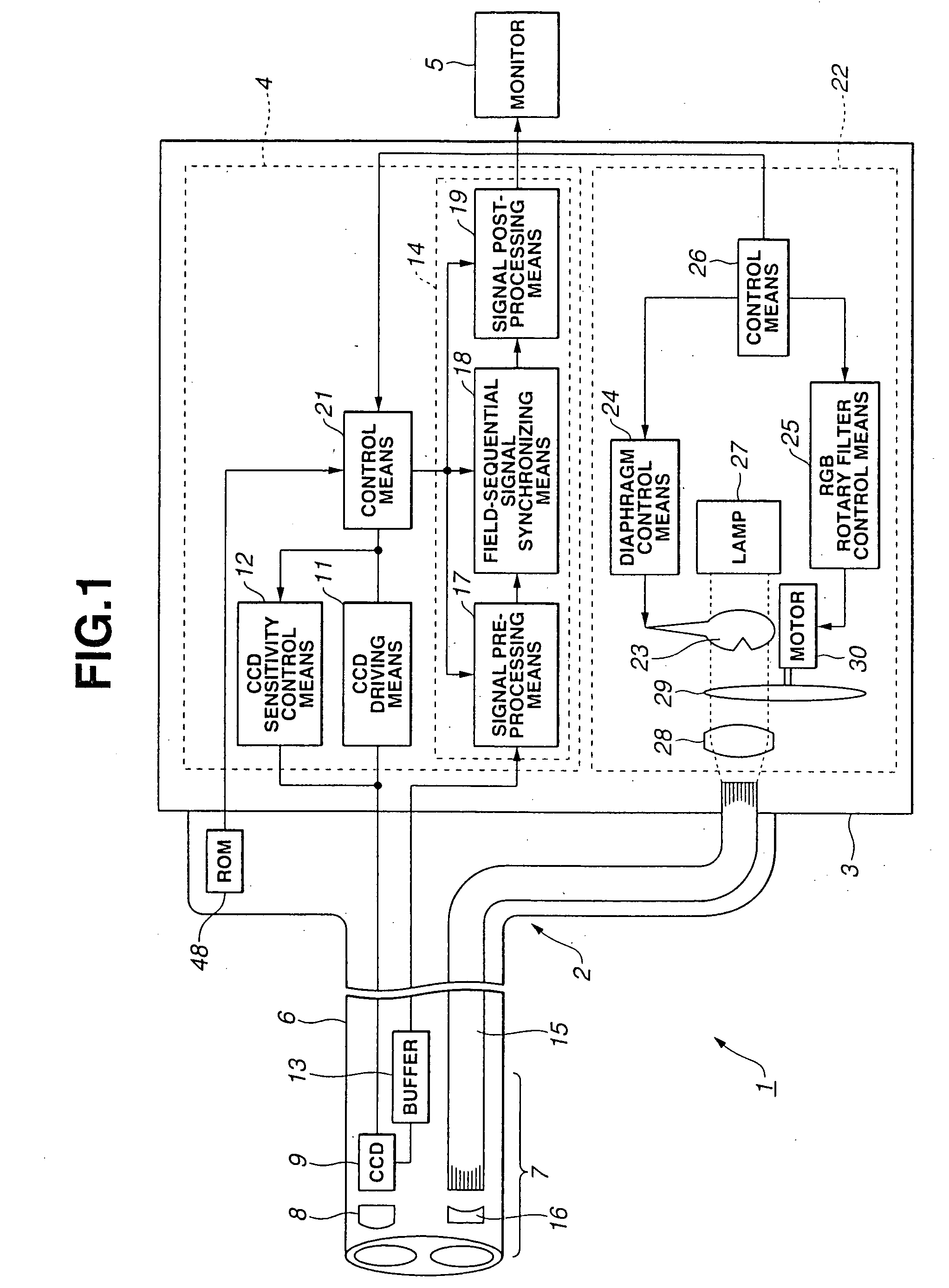
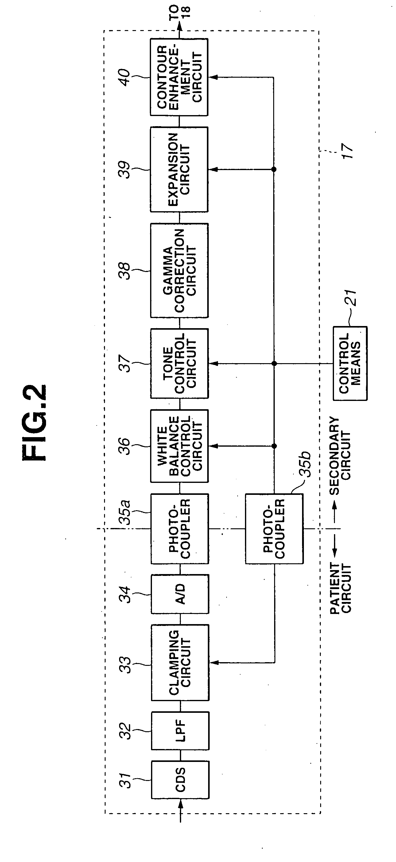
[0054] FIG. 1 to FIG. 6 are concerned with Example 1 of the present invention. FIG. 1 is a block diagram schematically showing the configuration of an endoscope system of Example 1. FIG. 2 and FIG. 3 show a signal pre-processing means included in a signal processing means. FIG. 4 shows various types of endoscopes employed in the present example. FIG. 5 describes the purposes of use of the endoscopes and others. FIG. 6 is an explanatory diagram concerning actions.

[0055] As shown in FIG. 1, an endoscope system 1 of Example 1 of the present invention consists mainly of an electronic endoscope (hereinafter, for brevity's sake, an endoscope) 2, a processor 3, and a monitor 5. A solid-state imaging device is incorporated in the endoscope 2. The endoscope 2 is connected to the processor 3 so that it can be disconnected freely, and a signal processing unit 4 and a field-sequential light source unit 22 are incorporated in the processor 3. The monitor 5 is connected to the processor 3, and a ...

Example

EXAMPLE 2

[0092] FIG. 7 shows the configuration of an endoscope system 51 in accordance with Example 2 of the present invention. The description of components identical to those shown in FIG. 1 will be omitted.

[0093] In Example 1, the field-sequential light source unit 22 is incorporated in the processor 3 together with the signal processing unit 4 including the signal processing means 14. In Example 2, a field-sequential light source unit 52 is included independently of the signal processing unit 4.

[0094] In the field-sequential light source unit 52, a half mirror 53 is disposed in front of the lamp 27. The half mirror 53 splits light emitted from the lamp 27. Light reflected from the half mirror 53 is routed to a light level sensor 54.

[0095] The amount of light emitted from the lamp 27 decreases with an increase in a lamp lighting time. The light level sensor 54 converts the decrease in the amount of light into numerical data. The numerical data is sent to the control means 21 via ...

Example

EXAMPLE 3

[0100] FIG. 8 shows the configuration of an endoscope system 51' in accordance with Example 3 of the present invention. The description of components identical to those shown in FIG. 1 and FIG. 7 will be omitted below. In Example 3, an LED light source unit 52' shown in FIG. 8 may be substituted for the field-sequential light source unit 52 of Example 2 shown in FIG. 7.

[0101] The LED light source unit 52' shown in FIG. 8 includes a red LED 57a, a green LED 57b, a blue LED 57c, and a condenser lens 28. The red LED 57a, green LED 57b, and blue LED 57c are connected to an LED control means 56 and lit sequentially. The condenser lens 28 converges the illumination light on the rear end of the light guide 15. Thus, field-sequential light rays are fed to the rear end of the light guide 15.

[0102] The iris diaphragm 23 is interposed between the red LED 57a, green LED 57b, and blue LED 57c and the condenser lens 28, and controlled by the diaphragm control means 24. The diaphragm cont...


PUM


Abstract

An endoscope 2 has a CCD 9 incorporated in the distal part of an insertion unit 6 thereof. The sensitivity of the CCD 9 can be varied by applying a plurality of pulsating driving signals so as to change an electron multiplication rate. The endoscope 2 is connected to a processor 3 so that it can be disconnected freely. Information representing a type of endoscope stored in advance in a ROM 48 is transmitted to a controller 21 incorporated in the processor 3. The control means 21 uses a CCD sensitivity control means 12 to control the sensitivity of the CCD 9 according to the type of connected endoscope 2. Consequently, a view image of proper brightness can be produced irrespective of the type of endoscope 2.

Description

[0001] The present invention relates to an endoscope system for visualizing an object using a solid-state imaging device whose sensitivity is controllable.[0002] An endoscope system having a solid-state imaging device consists mainly of an endoscope such as an electronic endoscope, a processor, a light source unit, and a monitor. In the endoscope system, the insertion unit of the endoscope is inserted into a body cavity, and illumination light emanating from the light source unit is irradiated to an object over a light guide lying through the endoscope. The solid-state imaging device incorporated in the distal part of the endoscope photoelectrically converts the light to produce a video signal. The processor processes the signal and displays an image on the monitor according to the signal.[0003] Talking of the endoscope system, a field-sequential endoscope system like the one disclosed in, for example, Japanese Unexamined Patent Application Publication No. 1-221135 is known as a mod...

Claims


Application Information

Patent Timeline
IPC IPC(8): A61B1/04A61B1/045A61B1/05A61B5/00G02B7/00G02B23/24H04N3/15H04N5/225H04N7/18
CPCA61B1/00059A61B1/0684A61B1/045A61B1/05A61B1/0638A61B5/0071A61B5/0084G02B23/24G02B23/2469G02B23/2484G02B26/008H04N3/155H04N7/183H04N2005/2255A61B1/0646A61B1/043A61B1/0655H04N23/555
Inventor DOGUCHI, NOBUYUKIKOMATSU, YASUONAKAMURA, KAZUNARITAKEHANA, SAKAEIMAIZUMI, KATSUICHIHANAWA, TAKAYUKI
Owner BAY CITY CAPITAL FUND IV
Why Eureka
Try Eureka