
Torch cale accommodating structure of arc welding robot

a technology of arc welding robot and arc welding torch, which is applied in the direction of cable arrangement between relatively moving parts, auxiliary welding devices, soldering apparatuses, etc., can solve the problems of difficulty in simulating the movement of torch cable, and high possibility of interference between torch cable and workpi

Inactive Publication Date: 2004-07-29
FANUC LTD
View PDF4 Cites 29 Cited by
  • Summary
  • Abstract
  • Description
  • Claims
  • Application Information

AI Technical Summary

Problems solved by technology

In such a case, a problem of interference tends to occur in association with movement of the arc welding robot.
In particularly, a torch cable connected to a welding torch has a high possibility that it interferes with a workpiece, a jig or a peripheral device in the vicinity of the torch cable, as compared with the distal end portion of a robot arm or the welding torch moving in a relatively narrow range.
Further, in case where a program for arc welding is prepared in an off-line manner, movement of the arm or the welding torch, an action of a wire feeding apparatus or the like can be simulated but it is difficult to simulate movement of the torch cable between the welding torch and the wire feeding apparatus.
Accordingly, in a stage where the program for arc welding is prepared in off-line, it is not easy to accurately estimate an interference possibility between the torch cable and peripheral objects in advance.
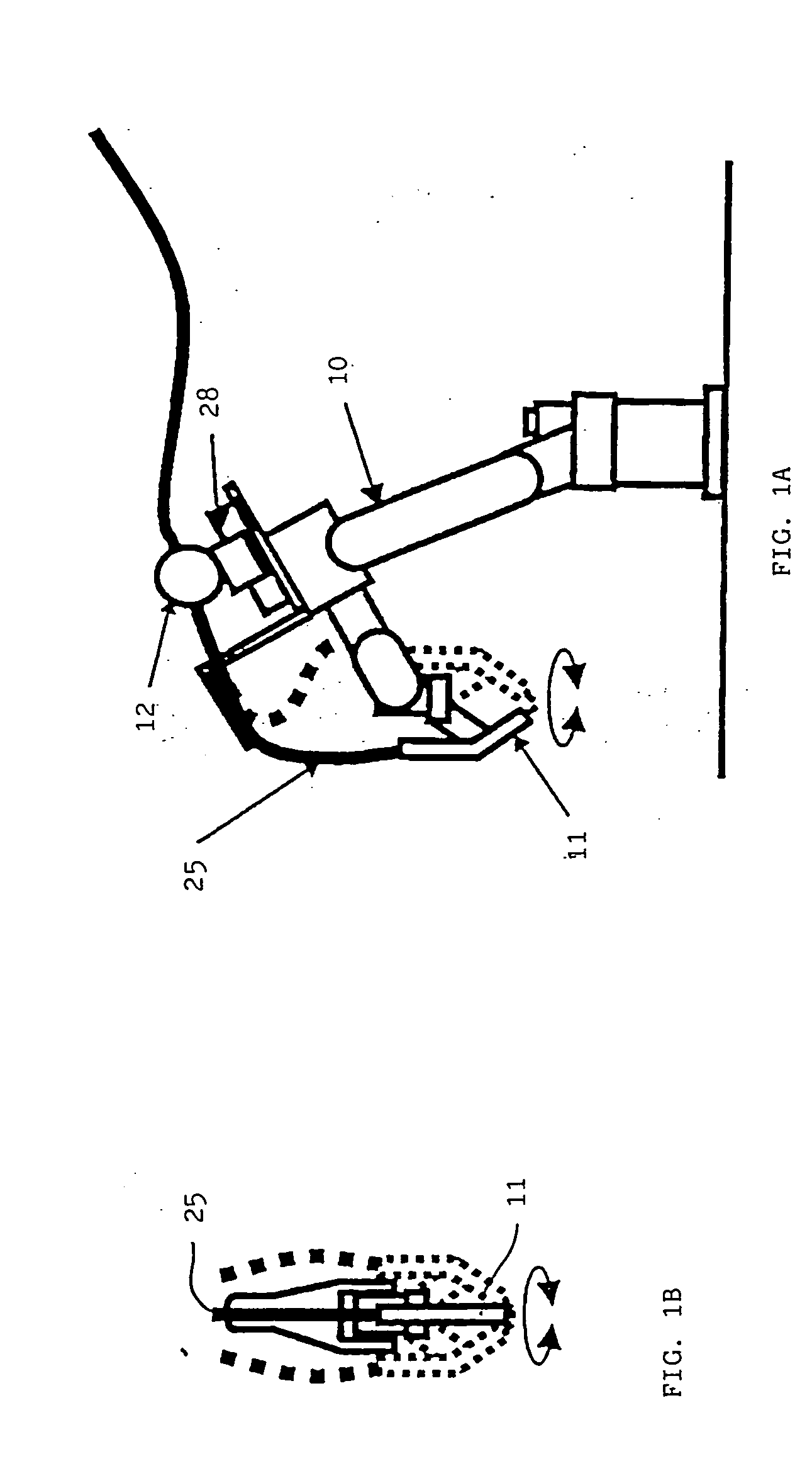
In the art described in the above-described Japanese Patent Application Laid-Open No. 09-216189, however, when an attitude of an axis of the robot wrist is changed, as shown by a dotted line in FIG. 1A and FIG. 1B, there is a problem that the behavior of the torch cable changes largely to interfere with the periphery thereof.
Further, in the art described in Japanese Utility Model Application Laid-Open No. 05-28563, since a torch cable projects largely relative to a front arm, such a possibility becomes high that the cable interferes with the periphery.
Therefore, in case where the attitude of the welding torch is changed during a welding workpiece, there may occur a problem obstructing a welding workpiece such that the torch cable is excessively pulled to twist about the front arm, or the torch cable excessively looses and its curvature changes largely, which causes a feeding inadequacy of the welding wire.
Further, when the attitude of the welding torch is changed, there is a problem that the behavior of the torch cable changes largely so that the torch cable interferes with a workpiece, a jig and a peripheral device.

Method used


Image

  • Torch cale accommodating structure of arc welding robot
  • Torch cale accommodating structure of arc welding robot
  • Torch cale accommodating structure of arc welding robot

Examples


Embodiment Construction

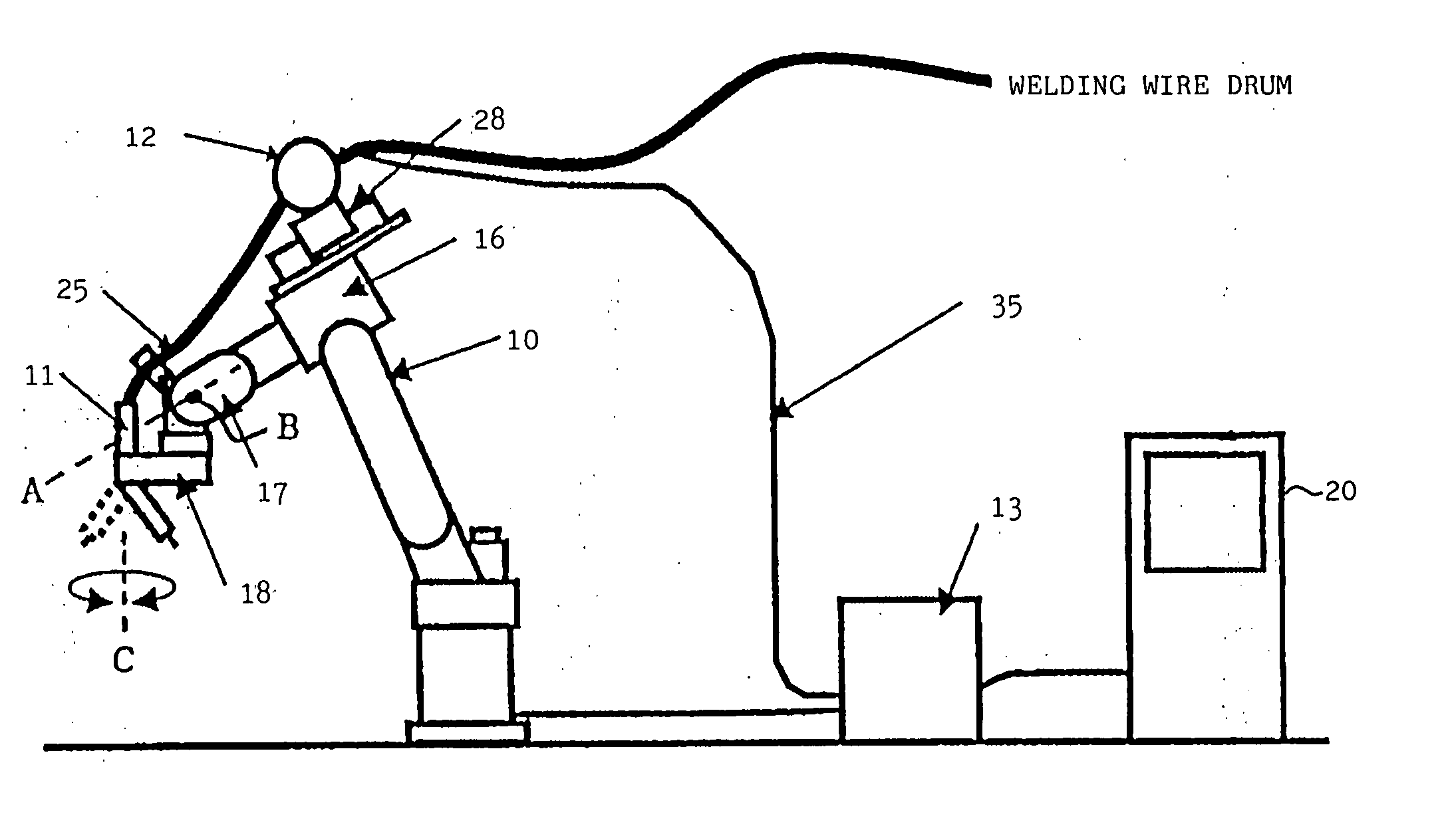
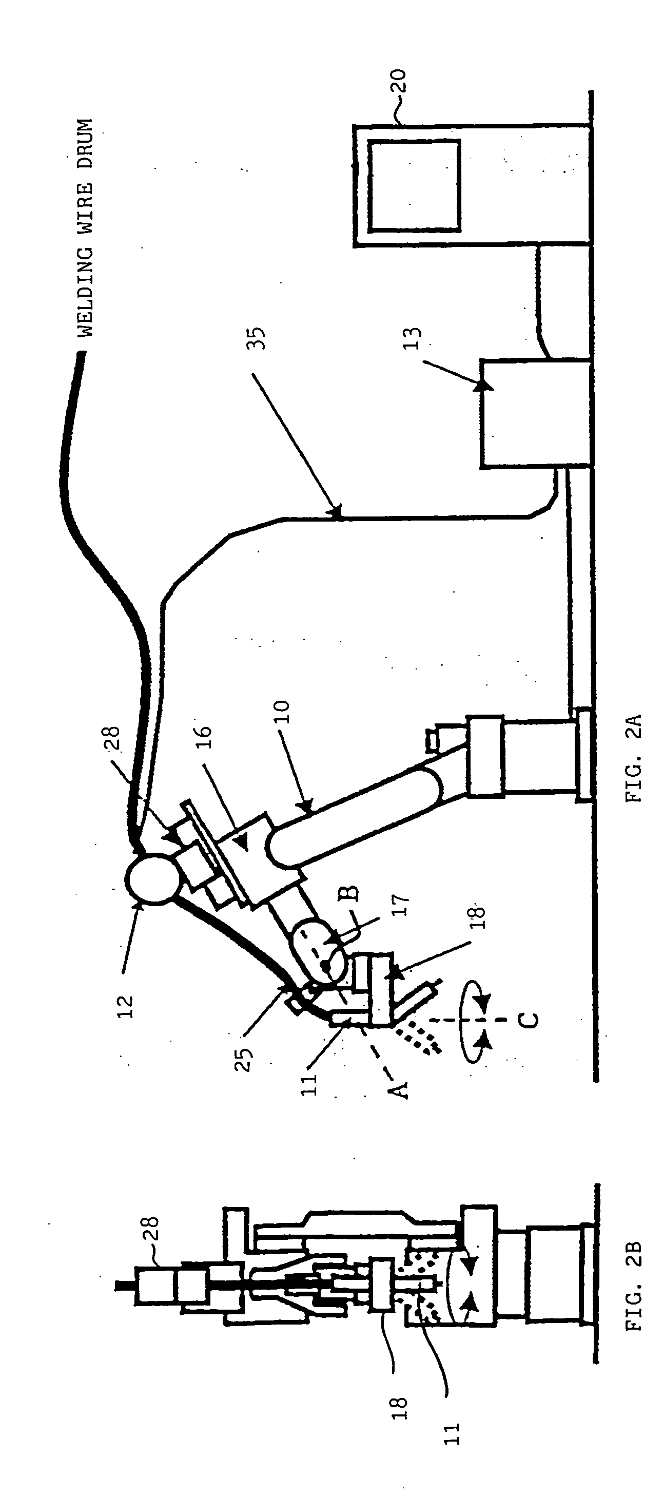
[0026] FIG. 2A and FIG. 2B are views showing a system constitution of an industrial arc welding robot having a torch cable accommodating structure according to one embodiment of the present invention. The system constitution of the industrial arc welding robot includes an arc welding robot (a robot mechanical section 10), a welding torch 11, a wire feeding apparatus 12, a welding power source 13 and a robot controller 20. The arc welding robot is a robot having the degree of freedom of six axes. Each axis is driven by a servomotor controlled by the robot controller 20 in a well-known aspect.

[0027] An operation program is taught to the robot controller 20, and the welding torch 11 mounted in the vicinity of a distal end of a wrist is moved to a target position according to the operation program and it performs an arc welding on a workpiece (for example, a joint (not shown)) with a designated attitude. Driving control of each servomotor conducted by the robot controller 20 is conducte...


PUM

PropertyMeasurementUnit
Structureaaaaaaaaaa

Abstract

A first wrist element is provided at a distal end of a front arm of an arc welding robot rotatably about a first axial line, a second wrist element is provided on the first wrist element rotatably about a second axial line, and a welding torch is supported on the second wrist element about a third axial line. A slide mechanism which can reciprocate in a direction approximately parallel to the first axial line is provided at a proper position from an upper portion of the front arm to an upper portion of the first wrist element and a wire feeding apparatus is mounted on the slide mechanism. By sliding the position of the wire feeding apparatus in response to the attitude of the welding torch, an extending state of the torch cable can be maintained properly.

Description

[0001] 1. Field of the Invention[0002] The present invention relates to a torch cable accommodating structure in an industrial robot mounted with a torch for arc welding.[0003] 2. Description of the Related Art[0004] As one of typical applications of a robot, there is an arc welding robot. The arc welding robot is an industrial robot which has a torch for arc welding (hereinafter, referred to as "a welding torch" simply) mounted in the vicinity of a distal end of an arm thereof for performing an arc welding on a workpiece.[0005] In an actual working site using an arc welding robot, there may by a case where a welding workpiece must be conducted in a state where an arm of the arc welding robot has been inserted in a narrow space such as a space in a workpiece, a space in a jig or a space in a peripheral device. In such a case, a problem of interference tends to occur in association with movement of the arc welding robot. In particularly, a torch cable connected to a welding torch has...

Claims


Application Information

Patent Timeline
IPC IPC(8): B23K9/12B25J13/00B23K9/133B23K9/28B23K37/02B25J19/00H02G11/00
CPCB23K9/1336B23K9/28H02G11/00B23K37/02B25J19/0025B23K9/287
Inventor INOUE, TOSHIHIKONAKAYAMA, KAZUTAKAHAGIHARA, MASAHIROTSUMURA, TAKESHI
Owner FANUC LTD
Learn More