

Collapsible tube with a distributor head without air return
a distributor head and tube technology, applied in the field of collapsible tubes, can solve the problems of particularly tight leakage of the pump attachment, and achieve the effect of less complicated, less expensive, and improved prophylactic protection of the product contained in the tub
Inactive Publication Date: 2004-07-29
CEBAL SA
View PDF4 Cites 17 Cited by
- Summary
- Abstract
- Description
- Claims
- Application Information
AI Technical Summary
Benefits of technology
[0014] The valve comprises a ring support and a sealing element which is supported (either closing it or not) above an opening formed in the said ring support, which is fixed on the inner surface of the head or close to the bottom of the neck, in other words at the bottom of the duct formed by the neck or near the neck, on the inner surface of the shoulder. The sealing element comprises a sealing means that forms an obstacle to product flow through the opening or hole formed in the ring support. There is no need to choose a sealing means shape such that it can be inserted in the hole (for example a conical insertion), since the displacement imposed on the sealing means when the user presses on the skirt is such that the skirt cannot easily return to exactly the same position. It is better to have a disk with a diameter significantly larger than the diameter of the hole. The hole diameter should preferably be approximately equal to or larger than the diameter of the port. A sealing means of this type can control the required distribution flow with a limited displacement.
[0038] Leak tightness is better maintained over the long term if the tube skirt and the shoulder comprise at least one layer made of a plastic material with a good gas diffusion barrier property, such as (ethylene-vinyl alcohol) copolymer (EVOH).
Problems solved by technology
The pump attachment is particularly leak tight due to the fact that the flange is embedded in the moulded cap.
Method used
View moreImage
Smart ImageViewing Examples

Examples
first embodiment
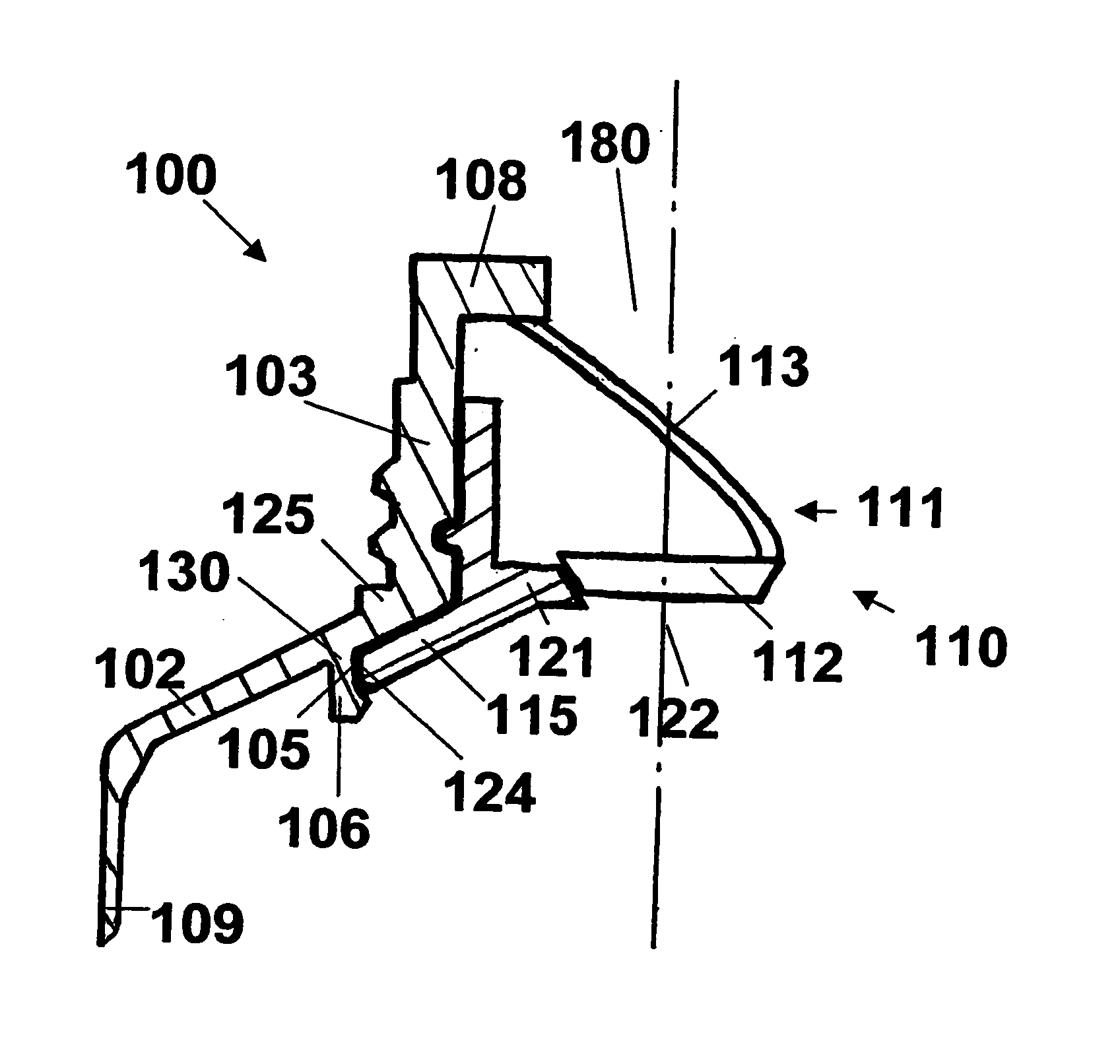
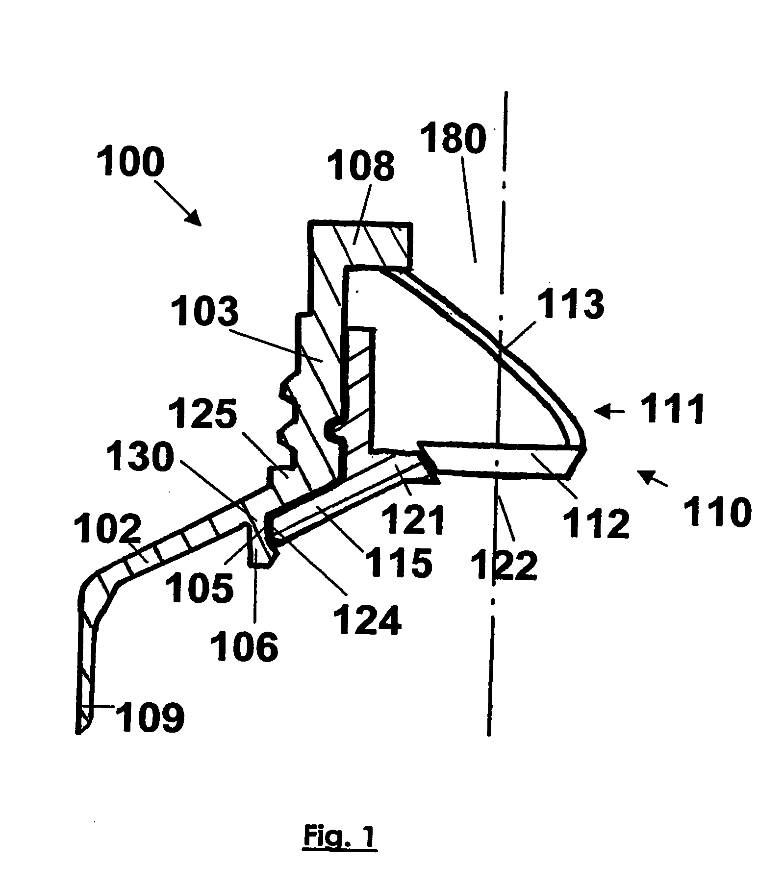
[0039] FIG. 1 illustrates a partial half-section along a diameter of a particular tube head according to the invention corresponding to the The sealing means and its elastic support element are not shown in section.
second embodiment
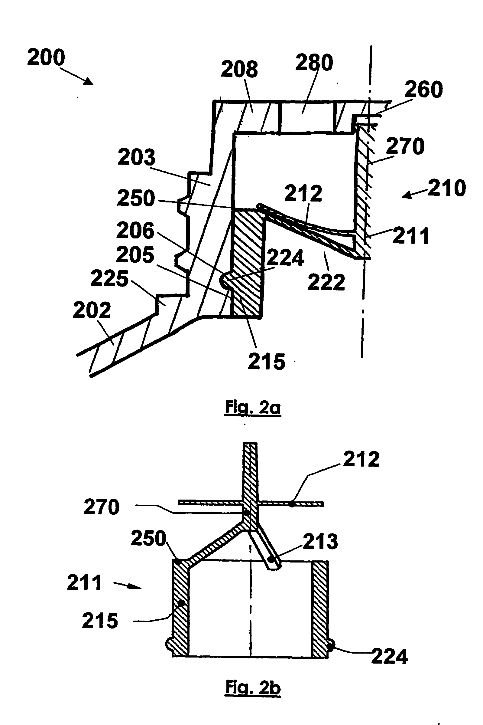
[0040] FIG. 2a illustrates a half-section along a diameter of a particular tube head according to the invention corresponding to the FIG. 2b shows the single piece valve after moulding and before being inserted in the neck.
third embodiment
[0041] FIG. 3 illustrates a half-section along a diameter of a particular tube head according to the invention corresponding to the
Login to View More PUM
 Abstract
Collapsible tube head (100, 200, 300, 400) comprising a neck (103, 203, 303, 403) which is fitted, with a port (180, 280, 380, 480) and a shoulder (102, 202, 302, 402). The aforementioned head is fitted with a valve (110, 210, 310, 410) which is inserted in the neck of the said collapsible tube, the said valve comprising a sealing means (112, 212, 312, 412) which is connected to a ring support (115, 215, 315, 415) having an opening (122, 222, 322, 422), the said sealing means being maintained in the closed position of the said opening when the tube is not compressed, and being maintained in the open position when the tube is compressed. The inner surface of the tube is provided with a bore (105, 205, 305, 405) which is disposed close to the base of the said neck. The ring support is fixed to the bore by means of bonding, soldering or force fitting, and the said bore and ring support are preferably provided with complementary connection means, in particular a groove and rice grains.
Description
TECHNICAL DOMAIN[0001] The invention relates to collapsible tubes for storing and distributing liquid to pasty products keeping them protected from ambient air. These tubes are fitted with non-return pumps or valves to prevent pollution from ambient air, firstly by preventing product that has been expelled from the port from returning inside the tube, and secondly by preventing air from entering due to relaxation of the pressure on the pump or the skirt.STATE OF THE ART[0002] Application FR 2 630 998 deposited by the Applicant discloses a tube comprising a skirt and a head equipped with a distribution pump provided with an annular flange. This head is fixed on the skirt of the tube and comprises a shoulder connecting the skirt to a plastic cap moulded on the annular pump attachment flange. The nature of the semi-rigid plastic material in the cap is the same as the nature of the surface layers of the body or the skirt. The flange of the pump is embedded in the cap, which is consequen...
Claims
Login to View More Application Information
Patent Timeline
 IPC IPC(8): B65D35/46B65D47/20B65D81/28
CPCB65D35/46B65D81/28B65D47/2075
InventorKERMAN, ERICMOUNIER, LAURESCHNEIDER, BERNARD
OwnerCEBAL SA