
Panel mounted shingles assembly with ventilating screen

a technology of ventilating screen and shingle panel, which is applied in the direction of vertical ducts, roofing, building components, etc., can solve the problems of unfavorable ventilation, unfavorable ventilation, and poor waterproofness of installation, and achieve the effect of improving the useful life of shingle panel assemblies

Inactive Publication Date: 2004-08-05
LES INDS MAIBEC
View PDF14 Cites 9 Cited by
  • Summary
  • Abstract
  • Description
  • Claims
  • Application Information

AI Technical Summary

Benefits of technology

[0004] The gist of the present invention is to improve the useful lifetime of shingle panel assemblies for building external walls.
[0005] A corollary object of this invention is to improve waterproofness of such shingle panel assemblies.
[0006] Another object of the present invention is to improve upon the stability of such a shingle assembly by reducing the likelihood of swelling of the shingle assembly components generated by unvented moisture therebehind.

Problems solved by technology

This is labour intensive and does not enable perfect waterproofness of installation.
The shingles may be offset or tilted relative to one another, providing an odd or unbalanced view.
Some moisture can become undesirably trapped between the water barrier membrane and the shingles, thus compromising the useful lifetime of the shingles, especially if keyway slots extend between each pair of successive shingle from a given horizontal row of shingles.
However, such shingles modules are still damaged quite rapidly by weathering forces, and are thus short lasting in useful lifetime due to moisture borne loads.
The reason for such inefficiency is that the layer of shingles is not per se waterproof, since a number of water seeping gaps exist along this first "line of defense" of the side wall.
This trapped moisture is what is deleterious to the useful life time of the shingles.

Method used


Image

  • Panel mounted shingles assembly with ventilating screen
  • Panel mounted shingles assembly with ventilating screen
  • Panel mounted shingles assembly with ventilating screen

Examples


Embodiment Construction

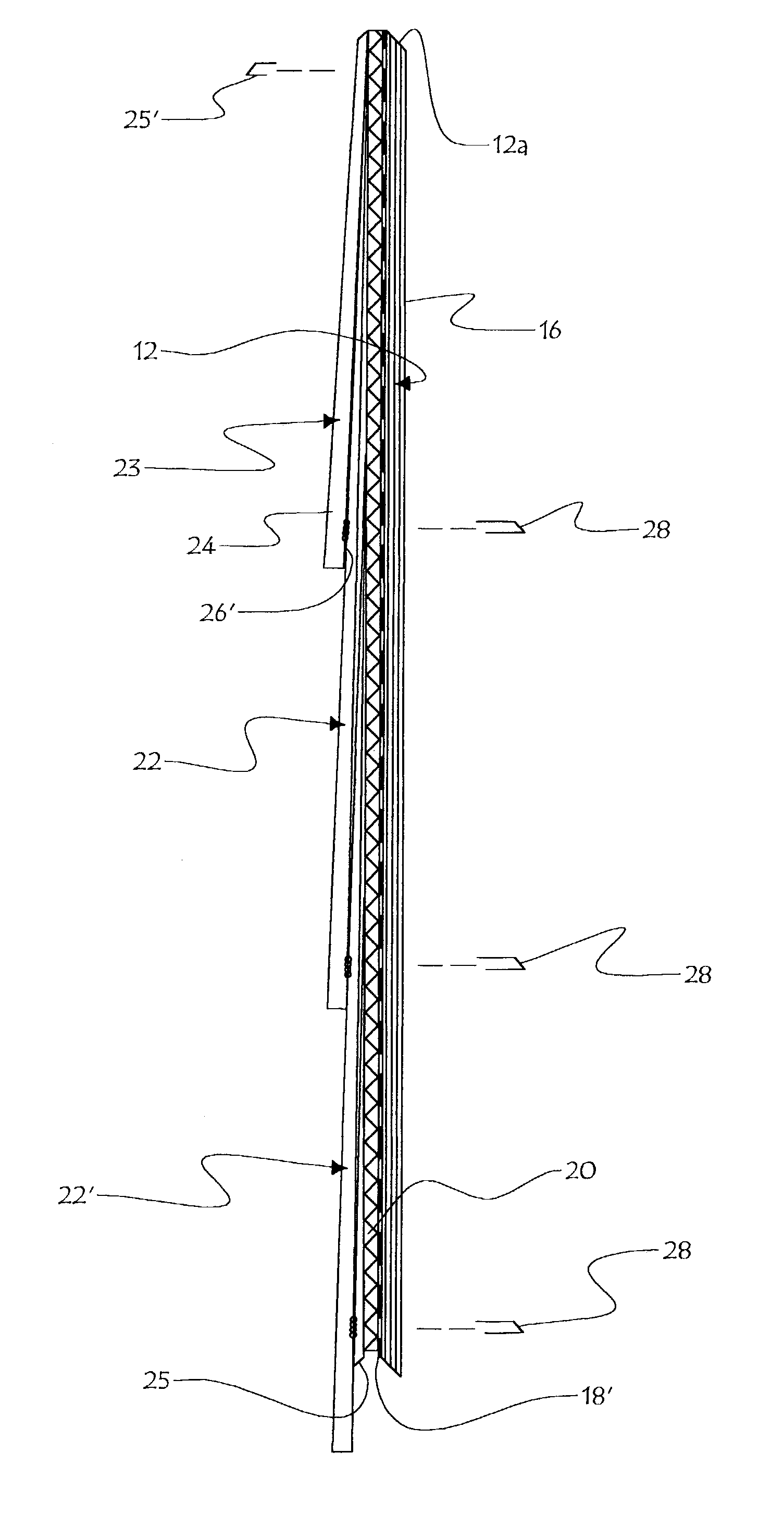
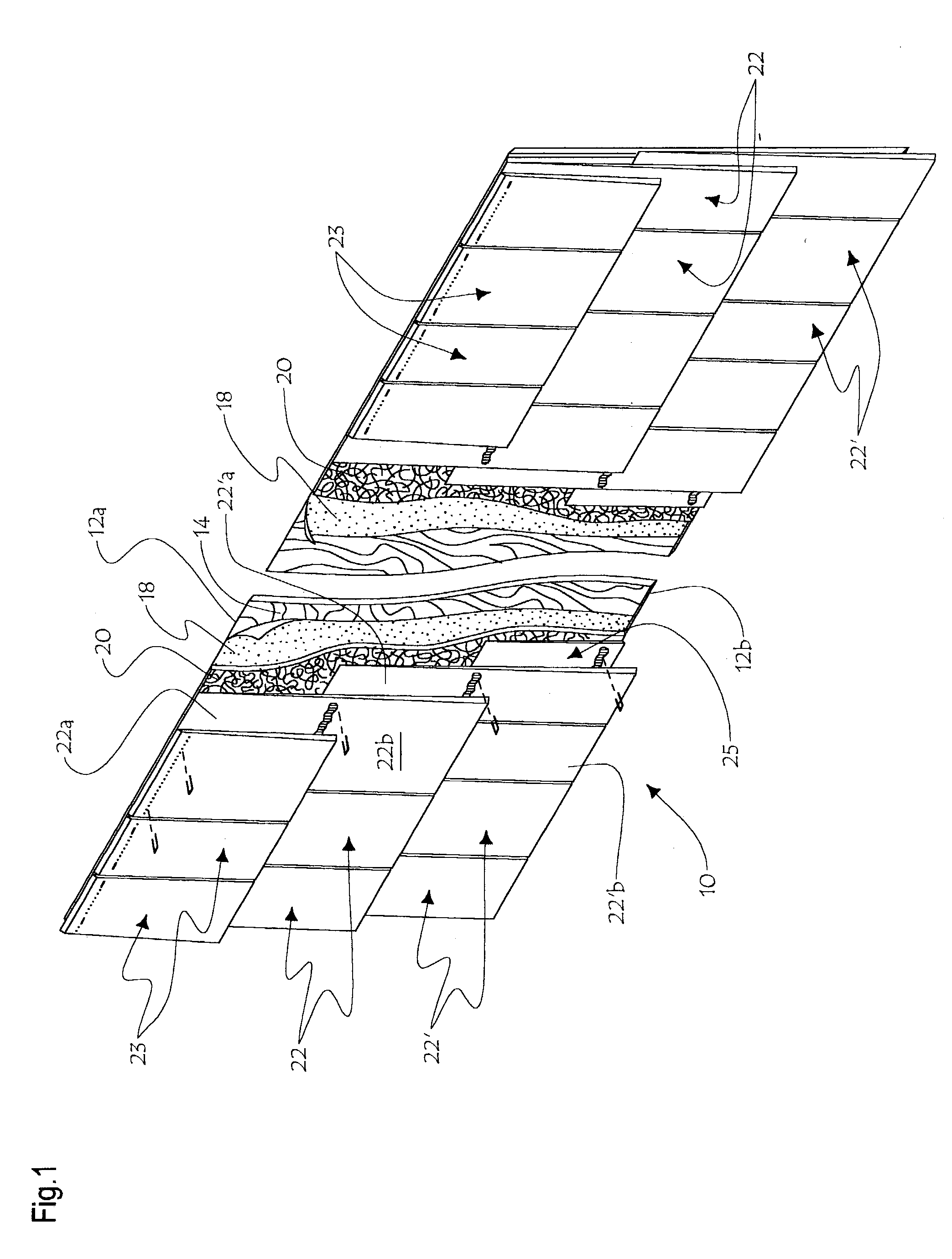
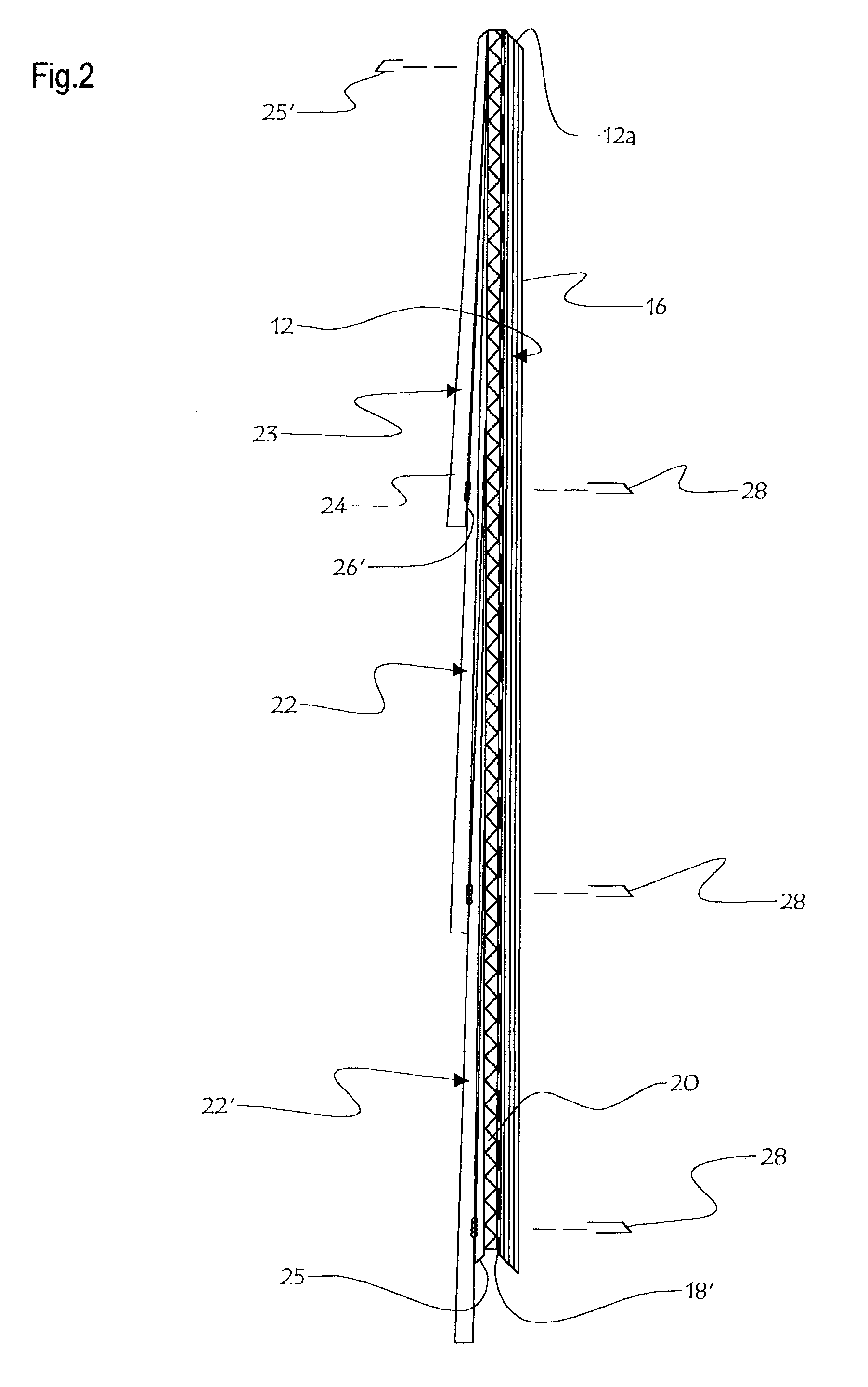
[0032] The assembly of board and shingles, 10 (FIGS. 1-2 and 4), or second assembly 110 (see FIGS. 3a-3b and 4 with corresponding references in the one hundred series) includes a continuous rigid sheet backer, for example a plywood board 12. Board 12 defines an inner face 14, an outer face 16, and a peripheral edge including a top edge 12A and a bottom edge 12B. Edges 12A, 12B, are preferably bevelled. Plywood board 12 may have, for example, a thickness of 1 centimeter (cm), a length of 250 cm and a width of 50 cm. A second sheet 18, forming a continuous water barrier membrane, for example a flexible perforated asphalt felt, is applied against the inner face 14 of board 12. Water barrier membrane 18 forms a continuous sheet, which may be approximately the same size in length as well as in width as the plywood backing board 12, to provide optimum moisture protection for the plywood board 12. A third sheet 20, forming a ventilating and self draining rainscreen membrane, for example a ...


PUM


Abstract

An exterior weather shielding panel assembly for fitting against an external side wall of a building, comprising a rigid back board for anchoring engagement with the building side wall, a waterproofing membrane applied against the back board, an air ventilating screen applied against the waterproofing membrane opposite the back board, and a plurality of shingles disposed against the screen outer face in slopewisely cascading fashion. Nails concealed by the overlapping sections of upper rows of shingles fixedly anchor the panel assembly components to the residential building side wall. The panel assembly is manufactured in factory before installation on the building.

Description

[0001] This invention relates to external wall coverings for buildings.[0002] In residential buildings, external side walls may be made from a variety of materials. Bricks or stone walls are common. However, in some historical districts of cities, standards may be set for compulsory wooden side walls. Wooden side-wall shingles are then recommended, to facilitate withstanding of weathering forces. A water barrier membrane is typically installed against the building side wall, and then the shingles are installed one by one by semi-skilled workers standing outside the building. This is labour intensive and does not enable perfect waterproofness of installation. The shingles may be offset or tilted relative to one another, providing an odd or unbalanced view. Some moisture can become undesirably trapped between the water barrier membrane and the shingles, thus compromising the useful lifetime of the shingles, especially if keyway slots extend between each pair of successive shingle from...

Claims


Application Information

Patent Timeline
IPC IPC(8): E04D1/26E04D3/35E04F13/08
CPCE04D1/265E04F13/0864E04D3/35E04F13/007E04D1/2916
Inventor JACQUES, DONALDMERCIER, RAYNALDMORIN, GERMAIN
Owner LES INDS MAIBEC
Learn More