Substrate process tank with acoustical source transmission and method of processing substrates

a technology of acoustical source and substrate, which is applied in the direction of cleaning hollow objects, cleaning using liquids, transportation and packaging, etc., can solve the problems of reducing production time, reducing the production efficiency of sub-conductor devices, and increasing the miniaturization of semiconductor devices

Active Publication Date: 2004-08-05
AKRION TECH
View PDF10 Cites 3 Cited by
  • Summary
  • Abstract
  • Description
  • Claims
  • Application Information

AI Technical Summary

Problems solved by technology

However, semiconductor devices are becoming more and more miniaturized.
These steps typically occur in a process tank and often require that each substrate undergo many cycles of cleaning, rinsing, and drying during processing so that particles that may contaminate and cause devices to fail are removed from the substrates.
Additionally, as the demand for semiconductor devices and the cost of labor increases, decreased production time has become a major concern in the semiconductor manufacturing industry.
However, decreased production time must be achieved without compromising the quality of the resulting product or the yield of properly functioning devices per substrate.
However, this set up has deficiencies with respect to the efficiency and effectiveness of the transmission of the megasonic energy from the transducers to the fluid.
Often, this bonding to the rigid plate is accomplished with less than ideal performance.
It has been discovered that the inefficient megasonic energy transmission of prior art systems is due in part to the differences in the Za of the materials through which the megasoinc energy must pass.
More specifically, large differences in the Za between consecutive materials through which the megasonic energy must pass results in increased impedance of the megasonic energy and ineffective energy transfer to the process fluid.
This results in an undesired energy loss when the megasonic energy passes between the different materials.
The rigid plates are not intended or designed to smooth the difference in transition of acoustical impedance between the piezoelectric crystals and the process fluid.
Depending on the application, this energy loss can result in less than optimal cleaning and / or less than optimal stripping rates.
Thus, existing systems that use megasonic energy to process substrates are less than optimal, resulting in energy transmission loss, increased energy usage, and / or less than optimal stripping and or cleaning performance.

Method used


Image

  • Substrate process tank with acoustical source transmission and method of processing substrates
  • Substrate process tank with acoustical source transmission and method of processing substrates
  • Substrate process tank with acoustical source transmission and method of processing substrates

Examples


first embodiment

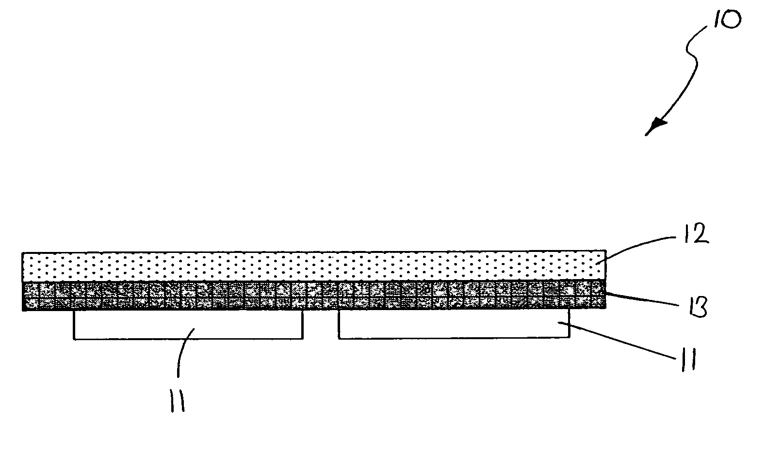
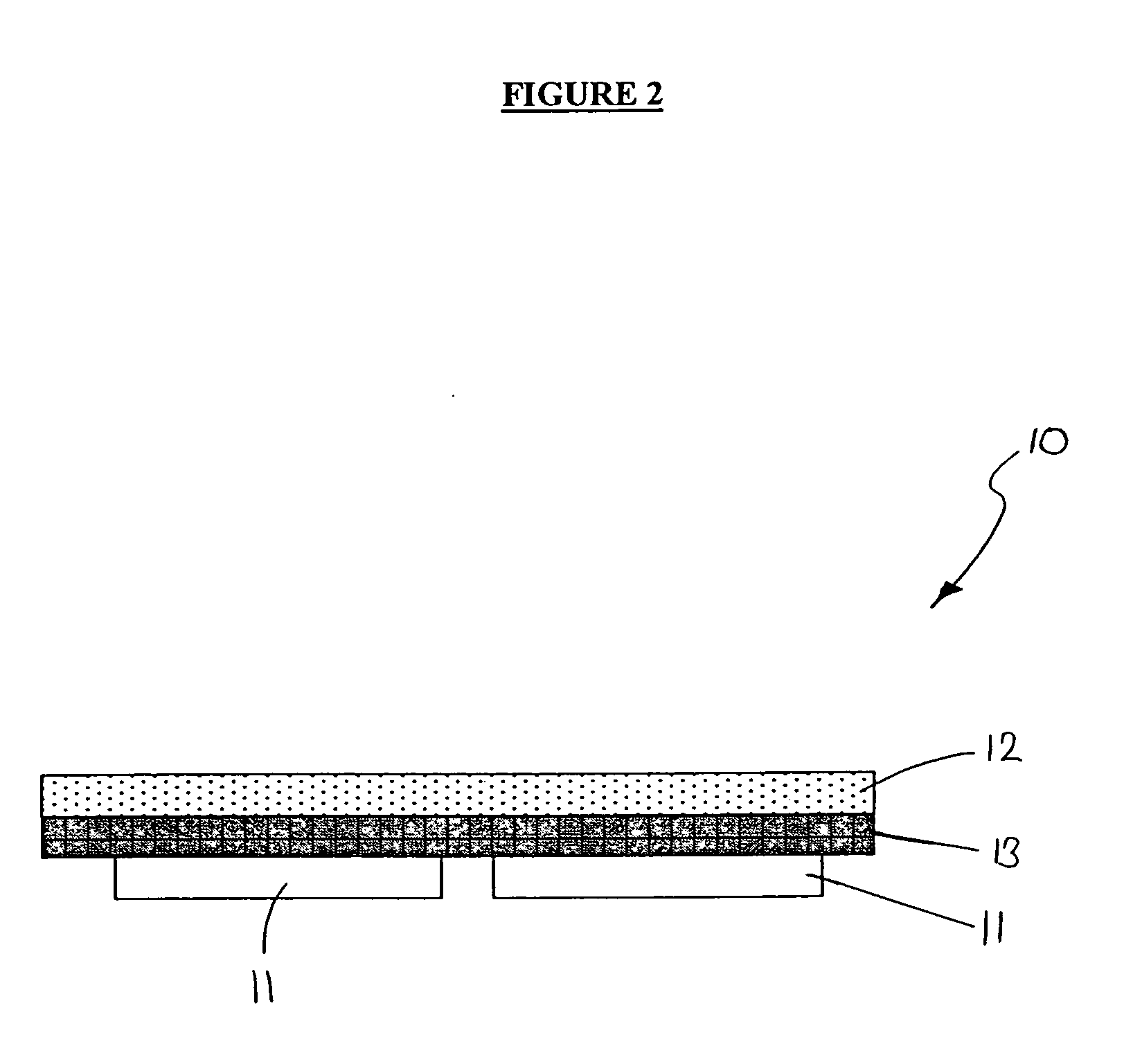
[0029] Referring to FIGS. 2 and 3, acoustical stack 10 is schematically illustrated according to the present invention. Acoustical stack 10 comprises two piezoelectric crystals 11, rigid plate 12, and transmission layer 13. Transmission layer 13 is positioned between piezoelectric crystals 11 and rigid plate 12. Piezoelectric crystals 11 are bonded to one side of transmission layer 13 while rigid plate 12 is bonded to the other side of transmission layer 13. Bonding is accomplished through the use of a bonding agent, such as epoxy. Once the acoustical stack 10 is assembled, acoustical stack 10 is coupled to a process chamber 20 so that the side of rigid plate 12 that is not bonded to the transmission layer 13 is in direct contact with that process fluid 21 that fills the process chamber 20. When crystals 11 are activated to produce acoustical energy, acoustical stack 10 will act as an acoustical energy pathway form the crystals 11 to the process fluid 21. When a substrate 22 is subm...

second embodiment

[0033] Turning now to FIG. 4, acoustical stack 40 is illustrated according to the present invention. Acoustical stack 40 comprises first transmission layer ("TL 1") 41 positioned between the crystals 11 and the rigid plate 12. Acoustical stack 40 also has a second transmission layer ("TL 2") 42 positioned on the other side of the rigid plate 12. When acoustical stack 40 is coupled to a process chamber, similar to the coupling illustrated in FIG. 3 for acoustical stack 10, the second transmission layer 42 of acoustical stack 40 will be in contact with the process fluid. In this embodiment, the first and second transmission layers 41, 42 are used to more gradually transition the Za between the crystals 11 and the process fluid. The system is designed so that Za.sub.Cystal>Za.sub.TL1>Za.sub.Rigid Plate>Za.sub.TL2>Z-a.sub.Process Fluid. In this embodiment, preferably, crystals 11 are piezoelectric crystals, first transmission layer 41 is made of aluminum, titanium, or beryllium, rigid p...


PUM

PropertyMeasurementUnit
acoustical energyaaaaaaaaaa
acoustical impedanceaaaaaaaaaa
transmissionaaaaaaaaaa

Abstract

A system and method for improving the efficiency and effectiveness of the transmission of acoustical energy to process fluids during substrate processing, such as cleaning or photoresist stripping. The invention utilizes a layered stack of materials to transmit acoustical energy from a source of acoustical energy to the process fluid. The material of which each layer is constructed is chosen so as to reduce the differences in acoustical impedance between consecutive layers of the stack, providing a more gradual transition, in terms of acoustical impedance, when acoustical energy is being transmitted from the source to the process fluid. In one aspect, the invention is a system comprising: a process chamber for receiving a process fluid; an acoustical energy source; and an acoustical stack having a first transmission layer and a second transmission layer that forms an acoustical energy pathway from the acoustical energy source to the process fluid in the process chamber.

Description

[0001] Benefit of Provisional Application Ser. No. 60 / 423,263 filed Nov. 1, 2002, is claimed.TECHNICAL FIELD OF INVENTION[0002] This invention generally relates to the field of substrate manufacturing, and specifically to methods and systems for improving the transmission of acoustical energy from an acoustical energy source to a process fluid during the processing of integrated circuits.BACKGROUND OF INVENTION[0003] In the manufacture of semiconductors, semiconductor devices are produced on thin disk-like substrates. Generally, each substrate contains a plurality of semiconductor devices. The exact number of semiconductor devices that can be produced on any single substrate depends both on the size of the substrate and the size of the semiconductor devices being produced thereon. However, semiconductor devices are becoming more and more miniaturized. As a result of this miniaturization, an increased number of semiconductor devices can be produced for any given area, thus, making th...

Claims


Application Information

Patent Timeline
Patent Type & Authority Applications(United States)
IPC IPC(8): B08B3/00B08B3/10B08B3/12B08B7/00B08B7/02B65DH01L21/00H04R25/00H10N30/00
CPCB08B3/12Y10S134/902H01L21/67057H04R25/00H10N30/00
Inventor KORBLER, JOHNGENG, XUECANG
Owner AKRION TECH
Why Eureka
Try Eureka