Parameter oriented graphical representation of hardware timing and triggering capabilities with contextual information

a hardware timing and contextual information technology, applied in the field of parameter oriented graphical representation of hardware timing and triggering capabilities with contextual information, can solve the problems of affecting the constraints imposed by the design of the device and the configuration of other attributes of the device are not generally considered or enforced, and users may still need substantial knowledge regarding the behavior or design of the hardwar

Active Publication Date: 2004-08-12
NATIONAL INSTRUMENTS
View PDF9 Cites 23 Cited by
  • Summary
  • Abstract
  • Description
  • Claims
  • Application Information

AI Technical Summary

Problems solved by technology

The configuration constraints imposed by the design of the device and by how other attributes of the device are currently configured are typically discovered by reading separate documents or by trial and error.
Although the examples described with reference to FIGS. 2-3 relate to graphical programs and / or graphical tools, e.g., LabVIEW graphical programs and configuration tools, it should be noted that in prior art approaches to configuring timing and triggering which use textual programming languages, e.g., the C programming language, the drawbacks are at least as significant, in that the user must typically determine which function calls to invoke, and which parameter values to set, in specifying timing and triggering for the hardware.
In other words, the user may still need substantial knowledge regarding the behavior or design of the hardware.
Thus, prior art techniques may provide access to the configurable attributes of a device, but do not generally include contextual information.
Additionally, constraints imposed by the design of a device and by configuration of other attributes of the device are not generally considered or enforced by prior art approaches and systems.
Prior art systems also do not typically propagate effects of a configured parameter to other aspects or parameters of the device.

Method used


Image

  • Parameter oriented graphical representation of hardware timing and triggering capabilities with contextual information
  • Parameter oriented graphical representation of hardware timing and triggering capabilities with contextual information
  • Parameter oriented graphical representation of hardware timing and triggering capabilities with contextual information

Examples


Embodiment Construction

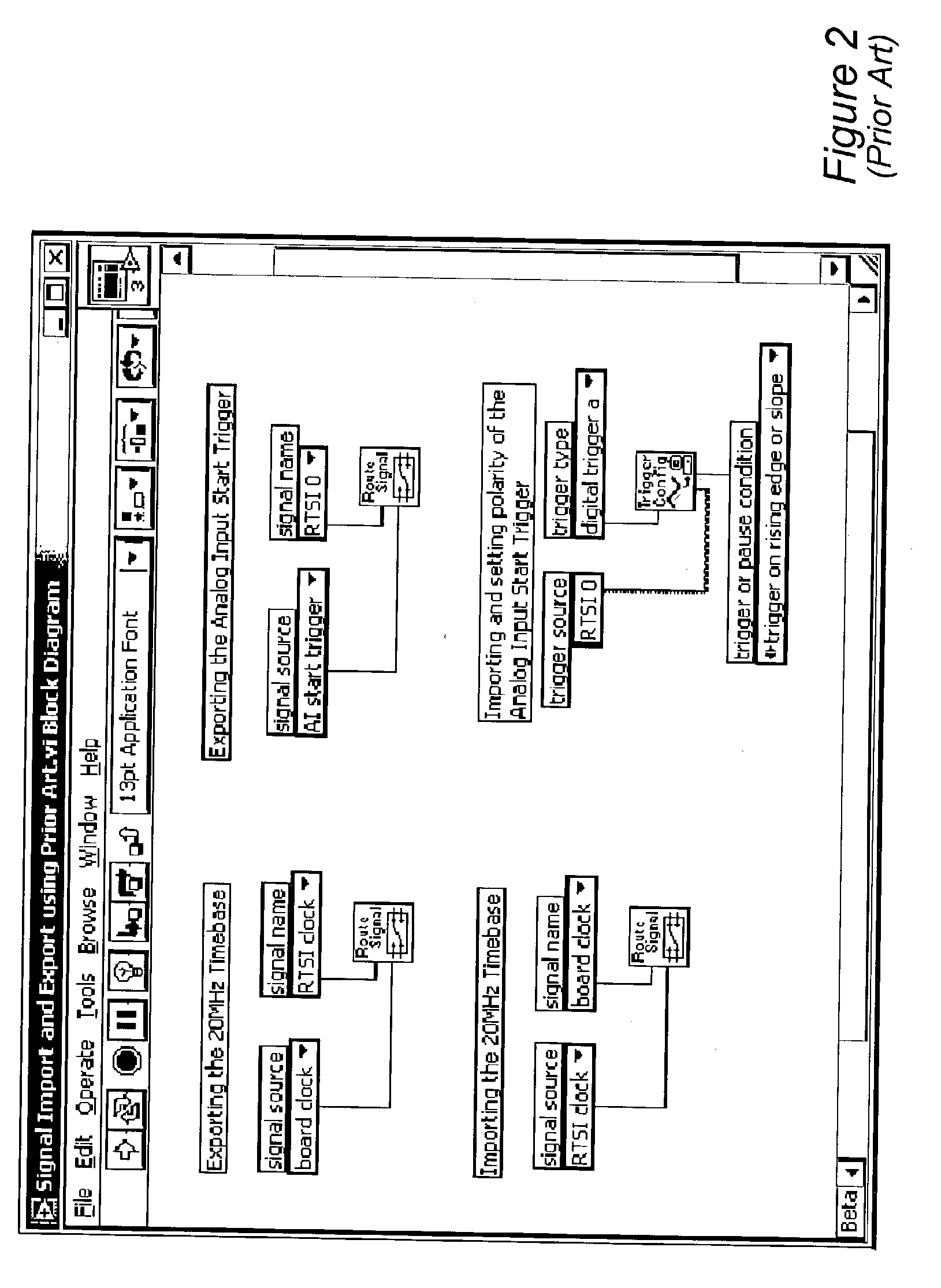
[0135] FIG. 9A illustrates an example prior art approach for configuring analog input timing for an E Series device (board). As FIG. 9A shows, a LabVIEW graphical program or block diagram includes various graphical program nodes, also referred to as VIs (virtual instruments), each representing and / or implementing a particular functionality for a measurement task or operation. In this example, a Single Scan VI or node is included in an execution loop, where data are acquired each time the Single Scan VI executes. Configuration of timing attributes is performed by entering values for various of the VIs or nodes in the program. Note that little if any contextual information is provided regarding the timing and triggering capabilities of the device, i.e., the E Series board. It is further noted that the block diagram of FIG. 9A is a complete program, and thus, a user is required to know at least the basics of graphical programming. It should be noted that in this example, default timing...


PUM


Abstract

System and method for graphically specifying hardware timing and triggering. A diagram is displayed graphically representing user-configurable timing and triggering components of a device, e.g., icons and signal paths representing operational relationships between the components, where timing and triggering for the device is determined by timing and triggering attributes. The diagram receives user input specifying one or more of the timing and triggering attributes, e.g., parameters, signal routes, etc., and the diagram modified, e.g., graphically configured, in accordance with the specified attributes, where the diagram represents configuration of the user-configurable timing and triggering components. Dependent attributes are programmatically computed based on the specified attributes. The specified attributes are stored and are usable to configure timing and triggering for the device. Program code for configuring the device may be generated based on the diagram. A state diagram may be displayed indicating effects of modifying the diagram on operation of the device.

Description

[0001] The present invention relates to the field of measurement and automation, and more particularly to a system and method for graphically representing and specifying hardware timing and triggering capabilities with contextual information.DESCRIPTION OF THE RELATED ART[0002] Increasingly, scientific and engineering tasks are performed using computer-based systems, where a computer system e.g., a personal computer or workstation, performs much of the processing, analysis, or control for applications. In many of these systems, the computer system includes or couples to one or more devices, and executes software to perform a desired function using the one or more devices. Such computer-based systems include, but are not limited to, test and measurement systems, automation systems, control systems, network management systems, and simulation systems, such as rapid prototyping systems, etc., among others. Such systems often use a device, such as a data acquisition (DAQ) hardware card o...

Claims


Application Information

Patent Timeline
Patent Type & Authority Applications(United States)
IPC IPC(8): G01R31/317G01R31/319G06F9/45G06F17/50
CPCG01R31/31724G06F17/5031G01R31/31912G01R31/31725G06F30/3312
Inventor HAYLES, TIMOTHY J.
Owner NATIONAL INSTRUMENTS
Why Eureka
Try Eureka