Flow cytomer with active automated optical alignment system

Inactive Publication Date: 2004-09-02
CYTOMATION +1
View PDF2 Cites 29 Cited by
  • Summary
  • Abstract
  • Description
  • Claims
  • Application Information

AI Technical Summary

Benefits of technology

0014] Another object of particular embodiments of the invention can be to permit alignment during normal flow cytometer operation, including but not limited to particle processing. In keeping with this object, a goal is to utilize a control scheme that may be employed without interfering with the flow cytometer processing to provide a very accurate level of alignment precision.
0015] A further object of particular embodiments of the invention can be to permit monitoring without impacting the quality of the measurements made by the flow cytometer system. This object has a goal of providing a non-int

Problems solved by technology

A significant problem with conventional flow cytometer systems can be that precise analysis of such scatter or fluorescence emission requires that the target area remain precisely aligned with the beam of electromagnetic radiation and that the scatter or fluorescence emission from irradiation of the target remain precisely aligned with the sensor.
First, the period of time that an operator expends to align a flow cytometer at the start of an operating period or during routine operation of the flow cytometer can be considerable.
The can amount to a significant portion of the operator's scheduled time on the instrument and can abbreviate or even preclude any actual analysis efforts.
Second, monitoring of alignment over long time periods, perhaps hours, can be difficult with the naked eye.
Even the smallest variations in alignment can render sensor signals useless or result in increased contamination of sorted particle populations.
On-the-fly alignment

Method used


Image

  • Flow cytomer with active automated optical alignment system
  • Flow cytomer with active automated optical alignment system
  • Flow cytomer with active automated optical alignment system

Examples


Embodiment Construction

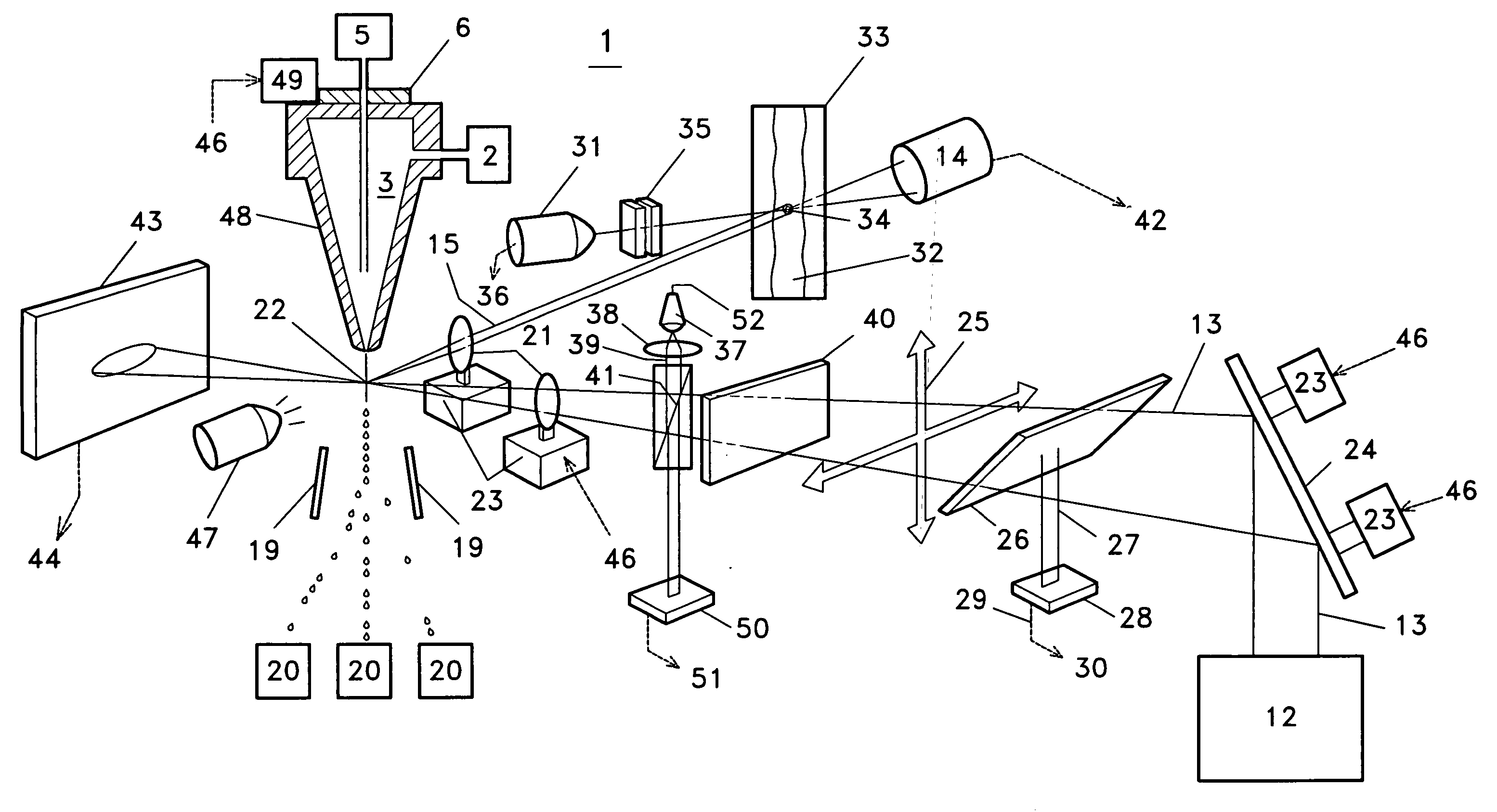
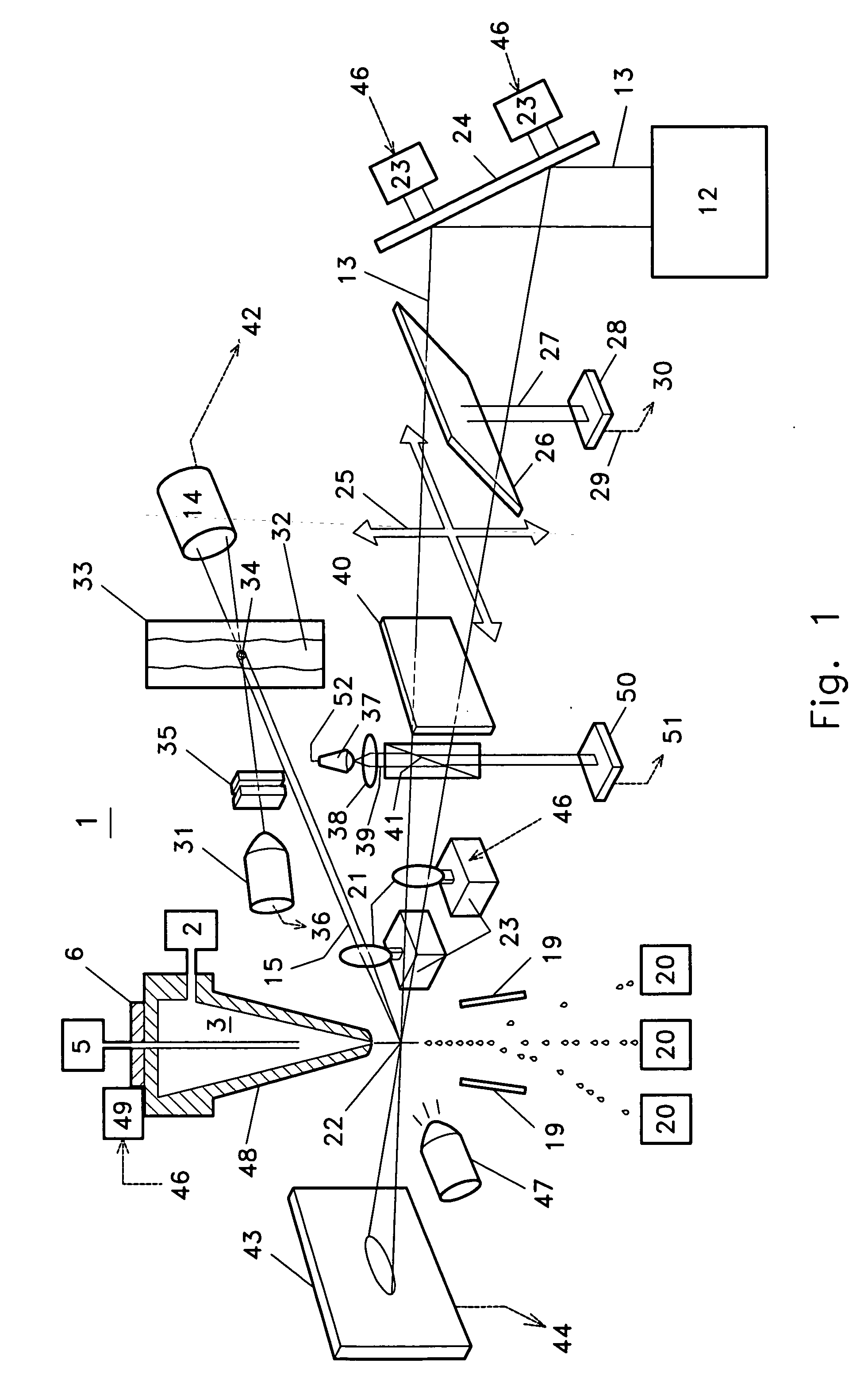
[0023] The invention provides an alignment and monitoring system which may be used with regard to various applications. While the description provides detailed examples in the context of droplet or continuous jet flow cytometer application, such examples are not meant to limit the use of the invention to applications in flow cytometry but should be understood to be illustrative of the broad range of applications in which the invention can be used.

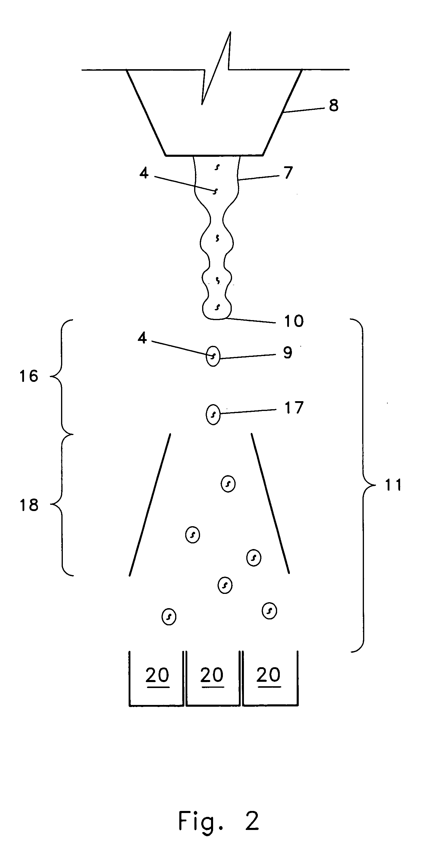
[0024] Now referring primarily to FIGS. 1 and 2, it can be understood that particular embodiments of the invention can provide an alignment and monitoring system that can be implemented in conjunction with a droplet or continuous jet flow cytometer(s). In a flow cytometer (1) embodiment of the invention, a fluid stream source (2) provides a fluid stream (3) into which particles (4) can be suspended. A source of particles (5) can insert the particles from time to time such that at least one particle becomes entrained in or is hydrodynamicall...


PUM


Abstract

An automated monitoring and alignment system to position the mechanical and optical components of a flow cytometer to enhance the consistency, performance, and efficiency of particle sorting and analysis applications.

Description

I. TECHNICAL FIELD[0001] An automated monitoring and alignment system to position the mechanical and optical components of a flow cytometer to enhance the consistency, performance, and efficiency of particle sorting and analysis applications.II. BACKGROUND[0002] Flow cytometry provides a method of analyzing and differentiating particles applicable to various clinical and research applications. Generally, flow cytometer systems irradiate particles and then sense the radiation emitted from the particle in order to identify particular physical attribute(s) of the individual particle(s) being studied. In particle sorting applications, each particle can be separated from the main population based upon the physical attributes identified as disclosed, for example, by U.S. Pat. Nos. 5,643,796; 5,602,349; and 5,602,039; and International Patent Application No. PCT / US95 / 13308, each hereby incorporated by reference.[0003] During operation of flow cytometers, hydrodynamic focusing entrains part...

Claims


Application Information

Patent Timeline
IPC IPC(8): G01N15/14
CPCG01N15/14G01N2015/149G01N2015/1452G01N15/1456
Inventor SHARPE, JOHNATHAN C
Owner CYTOMATION
Why Eureka
Try Eureka