Autoclavable endoscope

a technology of endoscope and endoscope, which is applied in the field of endoscopes, can solve the problems of affecting the accuracy of endoscopes, and unable to absorb transient shocks

Inactive Publication Date: 2004-09-09
INTUITIVE SURGICAL OPERATIONS INC
View PDF18 Cites 14 Cited by
  • Summary
  • Abstract
  • Description
  • Claims
  • Application Information

AI Technical Summary

Problems solved by technology

Experience has shown that repeated autoclaving of rigid endoscopes can damage seals whereupon steam can enter the endoscope with resultant condensation in the optical path distorting the image.
In addition endoscopes are often subject to mechanical shoc

Method used


Image

  • Autoclavable endoscope
  • Autoclavable endoscope
  • Autoclavable endoscope

Examples


Embodiment Construction

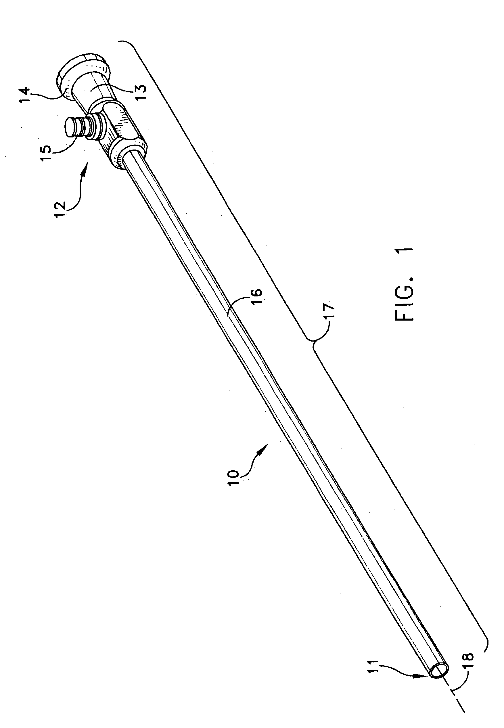
[0022] FIG. 1 depicts an endoscope 10 as it appears to medical personnel for use. It extends between a distal end 11, the end closest to the object to be imaged and a proximal end 12, the end closest to the person using the device. In this view an individual sees an optical body 13 with an eyecup 14 through which the image is viewed. A fiber post 15 receives an output connection from an illumination source thereby to provide light for transmission through optical fiber to illuminate the object being imaged. An outer tube 16 extends from the optical body. All of these elements constitute components of an outer housing subassembly 17 that extends along an optical axis 18.

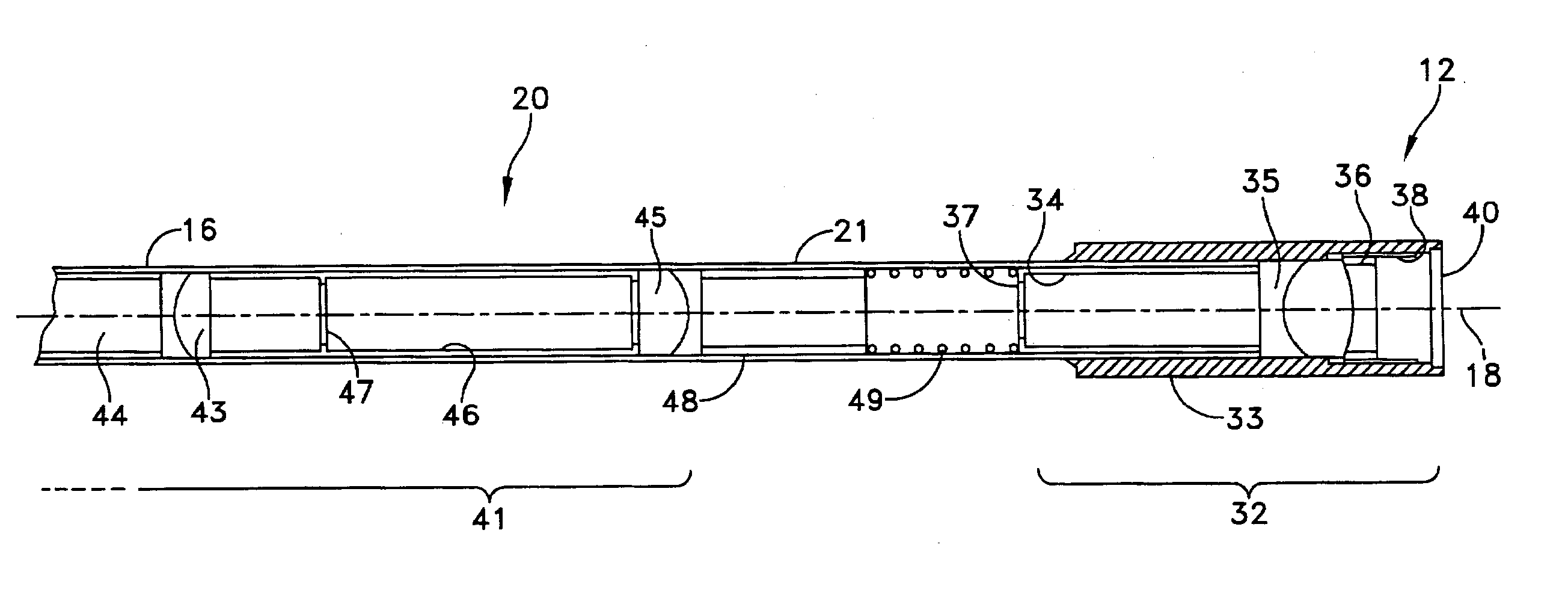
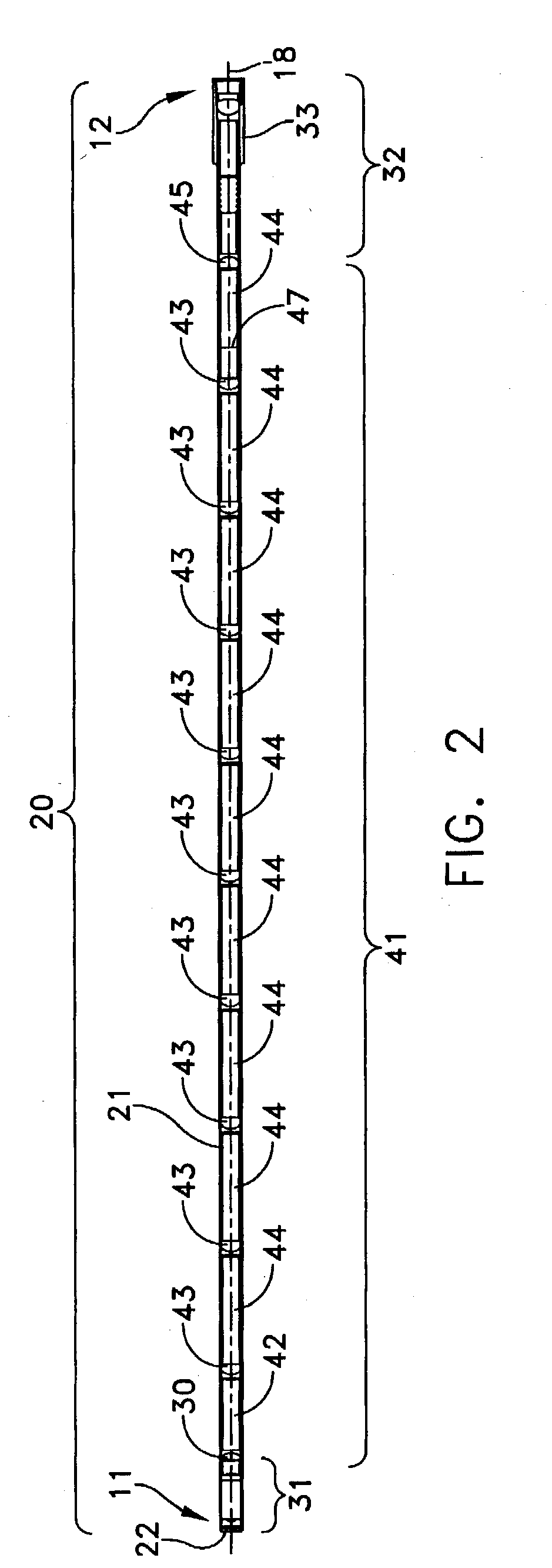
[0023] The endoscope 10 also houses an optics subassembly 20 as shown in FIG. 2. The optics subassembly 20 also extends between the distal end 11 and proximal end 12. FIGS. 2A and 2B depict portions of the optics subassembly 20 at the distal and proximal ends 11 and 12 in enlarged cross-sections, respectively. Specifi...


PUM


Abstract

A rigid endoscope includes an outer housing subassembly that supports an optics subassembly. The outer body subassembly includes concentric tubes with optical fiber for providing object illumination. The optics subassembly includes a tubular sheath sealed at both ends. A compression spring is positioned between a proximal most relay lens element and a distal most eyepiece element. The spring exerts a distally acting force on the elements of an optical objective and relay lens system. It also produces a proximally directed force on optical elements in the eyepiece. This minimizes differential thermal expansion stresses during autoclaving operations.

Description

[0001] 1. Field of the Invention[0002] This invention relates to endoscopes and more particularly to endoscopes adopted for sterilization by autoclaving.[0003] 2. Description of Related Art Endoscopes come in two basic forms. In one form the endoscope is flexible. Optical fibers transfer an image from an optical objective to an eyepiece or other viewing device. The fibers pixelate the image from the optical objective. Endoscopes of the second form are called rigid endoscopes. This invention, is applicable to rigid endoscopes. A rigid endoscope includes a tubular structure that carries an optical objective at a distal end and a relay lens system that transfers the image to a viewing device or eyepiece at a proximal end. Such devices provide better spatial resolution than flexible endoscopes do.[0004] Rigid endoscopes are used in various surgical and diagnostic-medical procedures, so it is important that devices be capable of being sterilized. There are different ways to sterilize med...

Claims


Application Information

Patent Timeline
IPC IPC(8): A61B1/00A61B1/002A61B1/12
CPCA61B1/00142A61B1/121A61B1/002
Inventor FORKEY, RICHARD E.ROSS, ROBERT N.CRUZ, SHERI A.
Owner INTUITIVE SURGICAL OPERATIONS INC
Why Eureka
Try Eureka