Methods and systems for providing emission of incoherent radiation and uses therefor

a technology of incoherent radiation and emission method, which is applied in the field of methods and systems for providing incoherent radiation and its use, can solve the problems of inability to meet the needs of many practical applications, and inability to meet the needs of many desired industrial processes, etc., to achieve the peak power of individual uv output pulses, high peak power uv output, and rapid rise time

Inactive Publication Date: 2004-09-23
MACQUARIE RES
View PDF11 Cites 31 Cited by
  • Summary
  • Abstract
  • Description
  • Claims
  • Application Information

AI Technical Summary

Benefits of technology

0105] To operate a dielectric barrier discharge (DBD) lamp, being a source of incoherent ultraviolet (UV) radiation, in a manner whereby the UV generated by the DBD appears in the form of single (and intense) pulses of short duration (e.g. 50-500 ns, more typically 40-70 ns) during each cycle of the lamp excitation, these pulses constituting high peak power UV output. The lamp geometry, operating conditions and procedures are optimised so as to maximise the peak power of the individual UV output pulses.
0106] This mode of operation is achieved through the use of pulsed electrical excitation (in particular using voltage pulses with rapid rise time) and by optimising the lamp operating parameters so as to increase the production rate (and shorten the formation time) of the dime

Problems solved by technology

Currently, commercial dielectric barrier discharge (DBD) lamp sources of incoherent ultraviolet (UV) are inherently low-peak power and are poorly suited to many practica

Method used


Image

  • Methods and systems for providing emission of incoherent radiation and uses therefor
  • Methods and systems for providing emission of incoherent radiation and uses therefor
  • Methods and systems for providing emission of incoherent radiation and uses therefor

Examples


examples

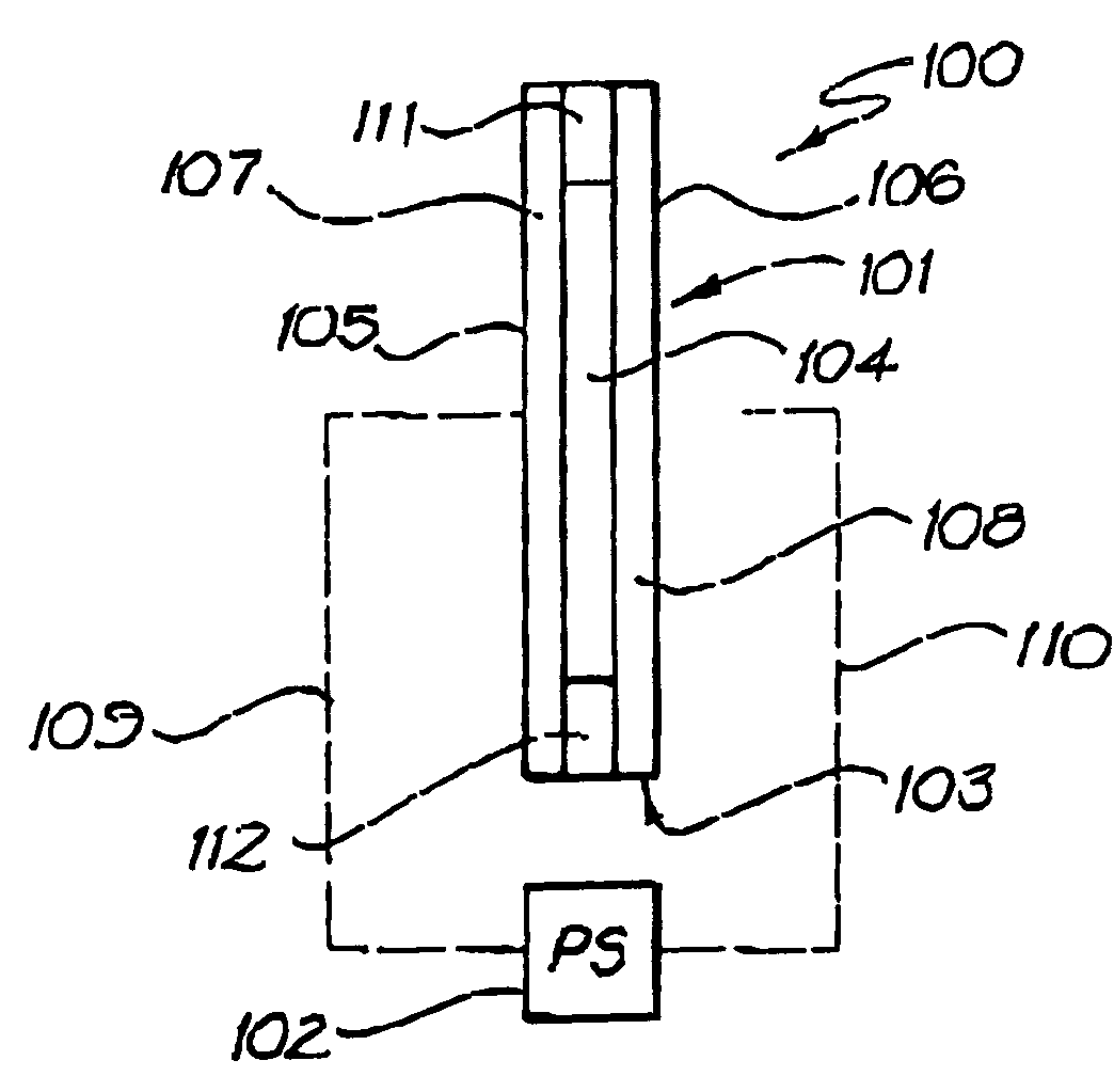
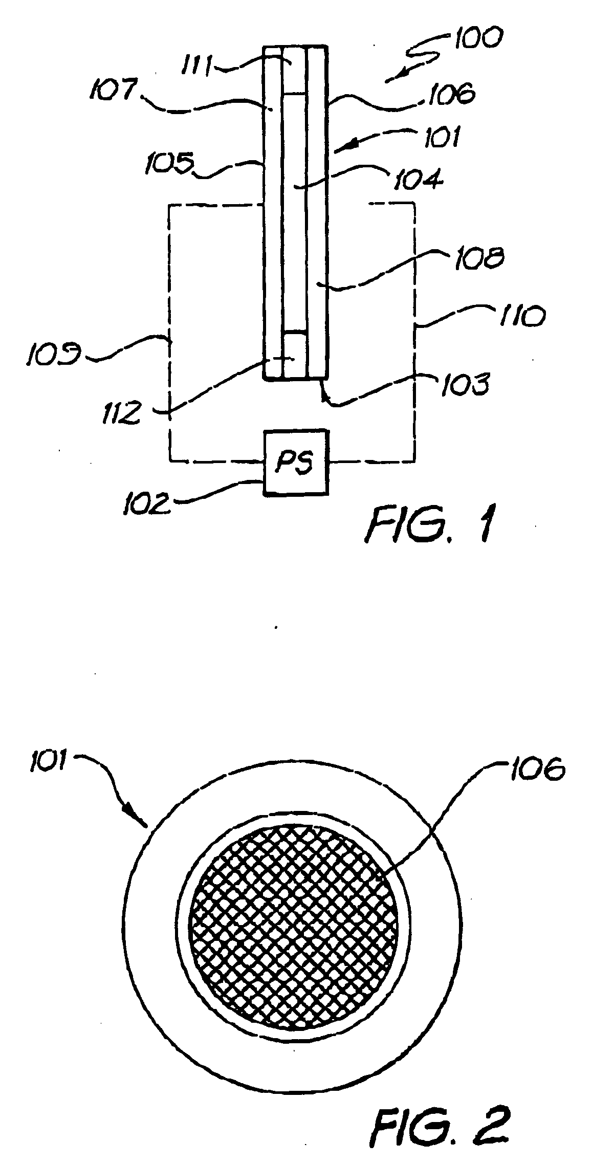
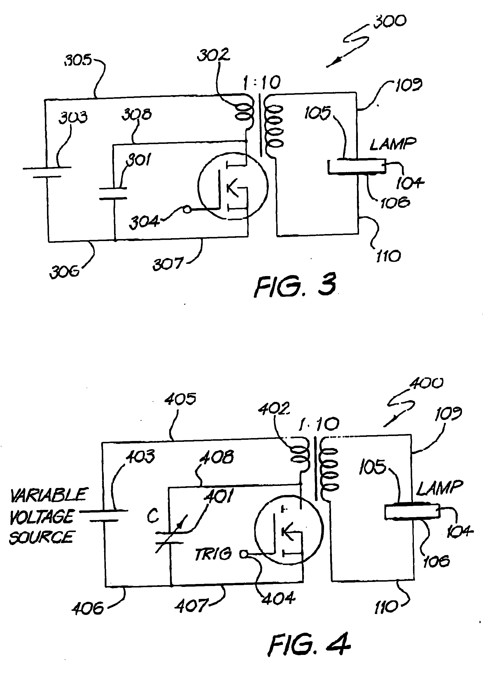
[0155] Measurements were performed on a system 100 as depicted in FIG. 1, which included a flat lamp 101 containing a 3 mm discharge gap in between two 2 mm thick dielectric windows made of Suprasil. The area of each electrode 105 and 106 was approximately 4 cm.sup.2. The lamp 101 was evacuated using a rotary pump (not shown) and filled with Xe (laser grade purity -99.9999%). A FET switched pulsed excitation circuit was used to provide voltage pulses to electrodes 105 and 106. The results are shown in FIGS. 5 to 11, and table 1. The results show that the short-pulsed excitation method leads to the production of a single pulse of VUV emission during each excitation cycle characterised by high peak power, compared to the VUV emission typically observed for AC excitation. The results also show that the operating conditions to optimise high peak power output are different to those required for optimising the overall efficiency. FIG. 5 illustrates the marked increase in high peak power V...


PUM


Abstract

Methods and systems for providing emission of incoherent radiation and uses therefor are disclosed. A system for providing emission of high peak power (in watts) incoherent radiation, comprises an electrically impeded discharge lamp linked to an electrical energy supply. The lamp comprises a discharge chamber which is at least partially transparent to the incoherent radiation, a discharge gas in the chamber, two electrodes disposed with respect to the chamber for discharging electrical energy therebetween, at least one dielectric barrier disposed between the two electrodes to electrically impede electrical energy passing between the two electrodes, an electrical energy supply capable of providing test risetime, high peak power unipolar voltage pulses, means of electrically linking the electrodes with the supply, the energy supply being capable of providing a sequence of high peak power unipolar voltage pulses from the energy supply to the electrodes and means to control (i interpulse period, and (ii) pulse risetime, whereby, in use, a substantially homogeneous discharge occurs between the two electrodes which causes emission of incoherent radiation pulses of high peak power from the lamp.

Description

[0001] This invention relates to methods and systems for providing emission of incoherent radiation and uses for therefor.[0002] Currently, commercial dielectric barrier discharge (DBD) lamp sources of incoherent ultraviolet (UV) are inherently low-peak power and are poorly suited to many practical applications. Alternative sources of high-peak power UV radiation (laser-based) are comparatively high-cost and not cost-effective for many desired industrial processes. Dielectric barrier discharge lamps to generate ultraviolet output generally employ electrical excitation schemes based on an AC voltage waveform (50 Hz-200 kHz). Although the I / V emitted by the plasma can be generated with high efficiency (.about.10-20%) and with high average power, the present inventors have realised that the UV output has inherently low-peak power due to the dynamics of the plasma excitation when using AC excitation.OBJECTS OF THE INVENTION[0003] It is an object of this invention to provide methods and ...

Claims


Application Information

Patent Timeline
IPC IPC(8): G21K5/00A61L2/08A61L2/10H05B41/24
CPCH05B41/24
Inventor KANE, DEBORAH MAREEMILDREN, RICHARD PAULCARMAN, ROBERT JOHN
Owner MACQUARIE RES
Why Eureka
Try Eureka