

Feedforward amplifier and radio communication apparatus with the amplifier
a radio communication apparatus and amplifier technology, applied in the direction of gated amplifiers, amplifier modifications to reduce non-linear distortion, transmission monitoring, etc., can solve the problems of wasteful power use for operating unnecessary error amplifiers, power consumption of main amplifiers occupies the greater part of the power consumption, and the distortion component falls within
- Summary
- Abstract
- Description
- Claims
- Application Information
AI Technical Summary
Problems solved by technology
Method used
Image

Examples
first embodiment
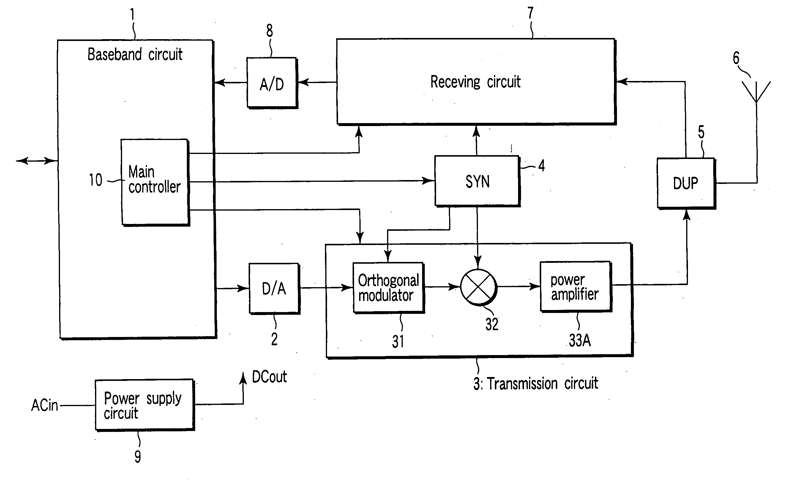
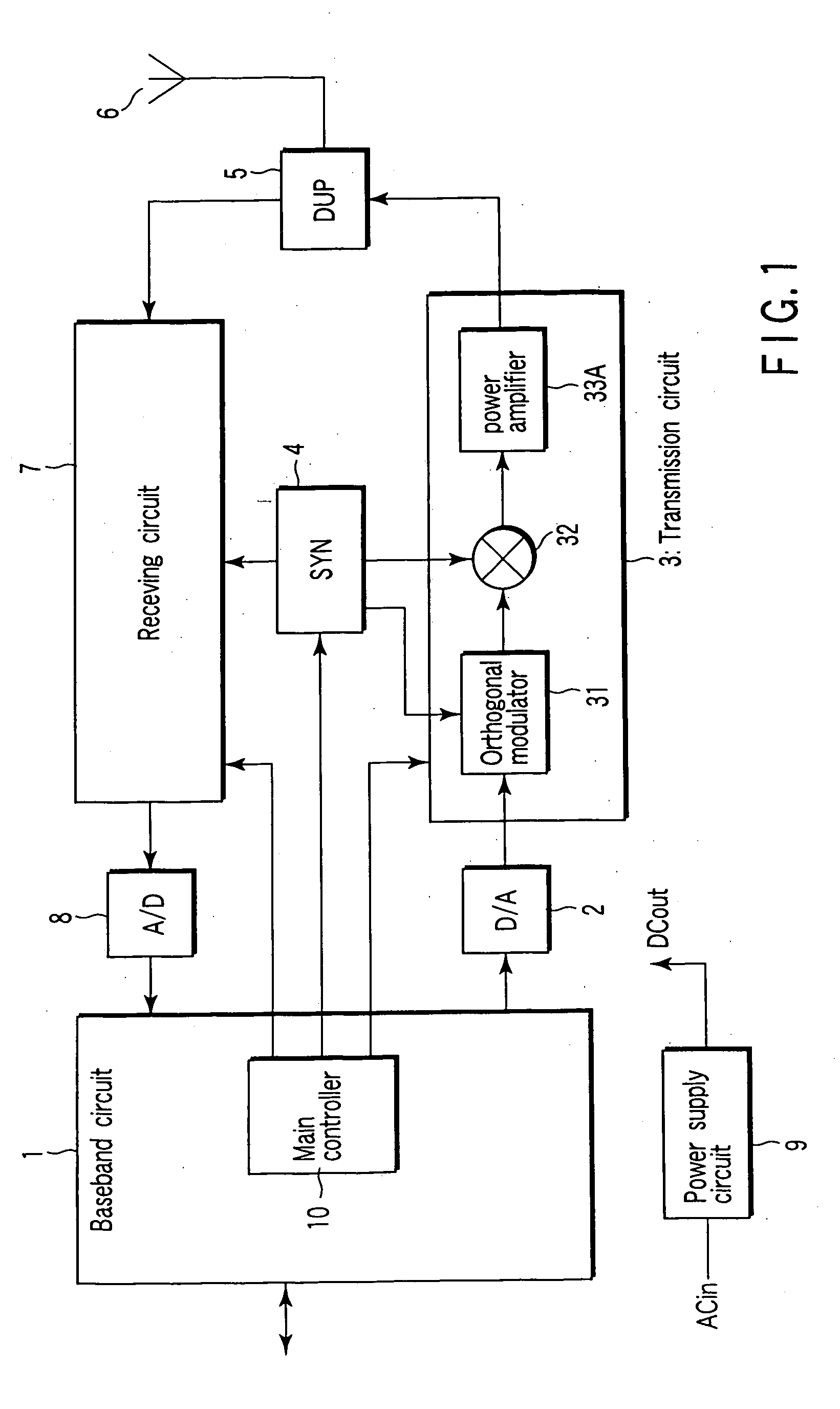
[0029] FIG. 1 is a block diagram illustrating the configuration of a radio communication apparatus provided in a mobile communication base station and equipped with a feedforward amplifier according to the invention.
[0030] In FIG. 1, the data supplied from a wired communication network (not shown) is input to a baseband circuit 1, where it is subjected to encoding for compression, and to spread encoding for enabling communication using code-division multiple access (CDMA). The data (signal) obtained after spread encoding is converted into an analog signal by a digital-to-analog converter (DAC) 2, and then input to a transmission circuit 3.
[0031] The transmission circuit 3 comprises an orthogonal modulator 31, frequency converter 32 and power amplifier 33A. The analog data signal input to the circuit 3 is first subjected to orthogonal modulation in the orthogonal modulator 31, and then converted into a radio signal in the frequency converter 32. The frequency conversion is performed ...
second embodiment
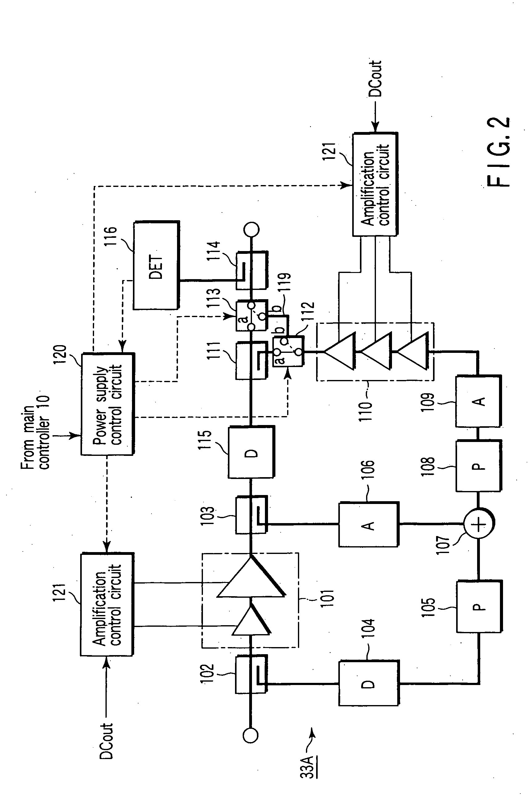
[0077] FIG. 10 is a block diagram illustrating a feedforward amplifier 33D according to a second embodiment of the invention. In FIG. 10, elements similar to those in FIG. 2 are denoted by corresponding reference numerals, and no detailed description is given thereof.
[0078] In the power amplifier 33D of this embodiment, an amplifier 110A having a plurality of amplifiers 1101, 1102 and 1103 is provided, and a switch (switch circuit) 1104 is provided in the error amplifier 110A for changing the number of connected amplifiers 1101-1103 in the amplifier 110A. An amplification control circuit 120A switches the switch 1104 to change the number of connected amplifiers 1101 to 1103.
[0079] By virtue of this configuration, the transmission power can be changed between two levels by changing the number of connected amplifiers 1101 to 1103, when a radio signal is transmitted with power corresponding to, for example, a small cell.
[0080] For example, when a radio signal is transmitted at a first ...
third embodiment
[0085] FIG. 11 is a block diagram illustrating a feedforward amplifier 33E according to a third embodiment of the invention. In FIG. 11, elements similar to those in FIG. 2 are denoted by corresponding reference numerals, and no detailed description is given thereof.
[0086] The feedforward amplifier 33E of the third embodiment differs from the first embodiment in that in the former, the bypass line 119 for bypassing the directional coupler 111 is directly connected to the radio signal line output without the switch 113. In the third embodiment, the length of the bypass line 119 is set to, for example, 1 / 4 of the wavelength of a radio signal, in order to prevent impedance miss match from occurring in the radio signal output line, because of the bypass line 119 when the movable contact of the switch 112 is connected to the stationary contact "a".
[0087] To prevent impedance miss match, a capacitor 117 may be provided across the bypass line 119 as shown in FIG. 12, or an open stub 118 ma...
PUM
 Abstract
Description
Claims
Application Information