

Torque transmission coupling
a transmission coupling and torque technology, applied in the direction of dashboard fitting arrangement, jet propulsion mounting, gear mounting, etc., can solve the problems of the pair of gears performing the relative rotation to be much decelerated, and the difficulty of installing the decelerating mechanism in a narrow spacing in the transfer devi
- Summary
- Abstract
- Description
- Claims
- Application Information
AI Technical Summary
Benefits of technology
Problems solved by technology
Method used
Image

Examples
first embodiment
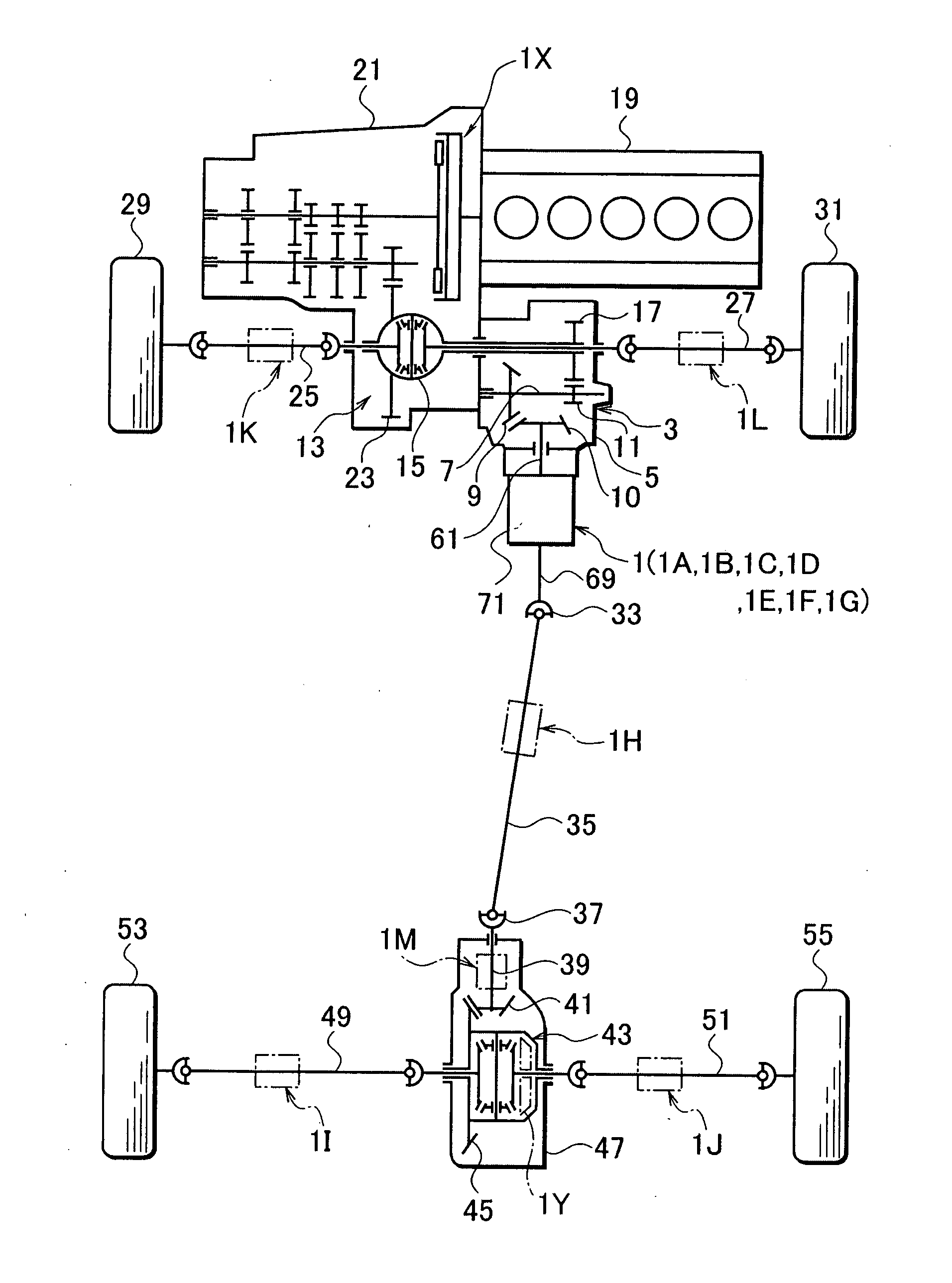
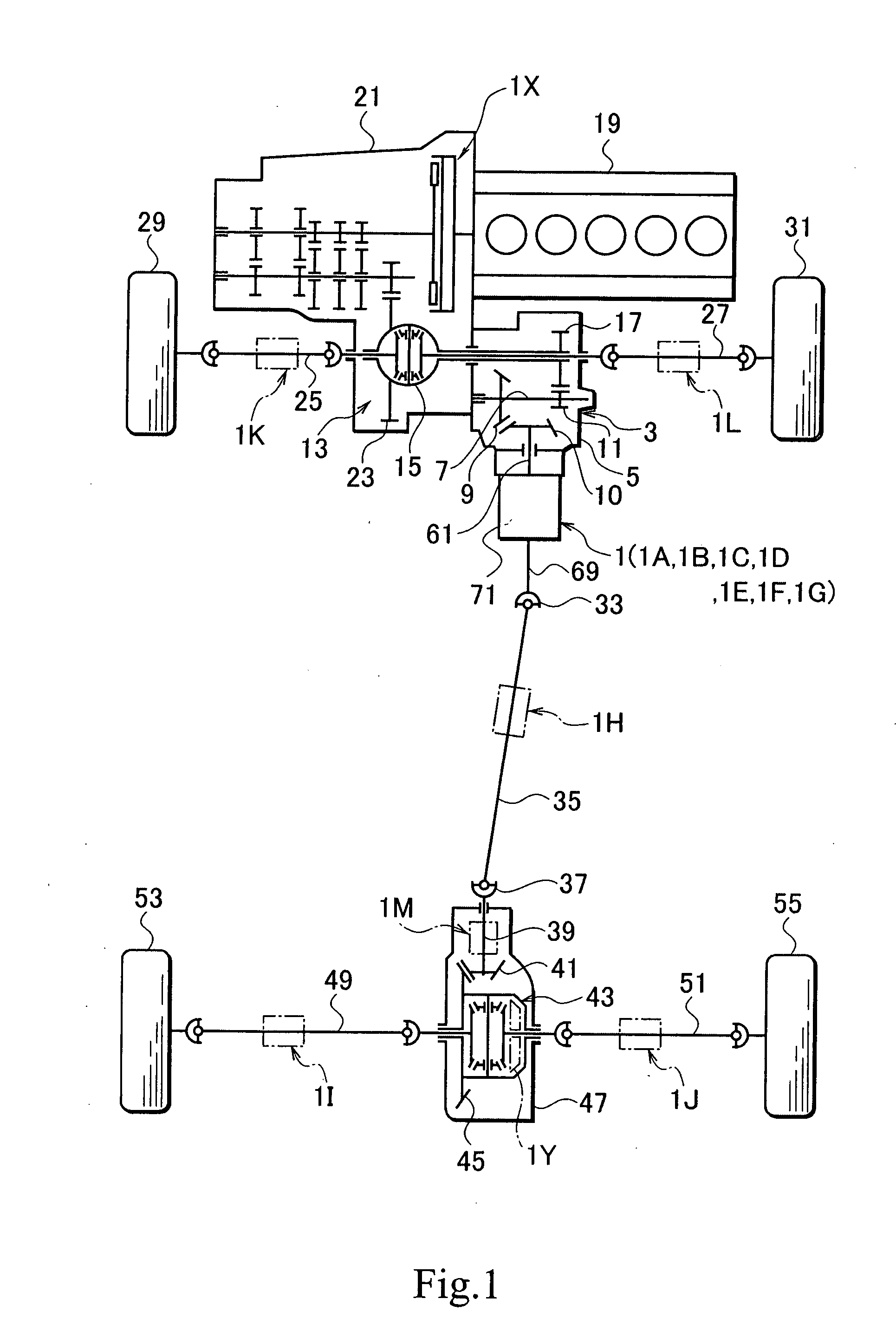
[0084] FIG. 1 is a skeleton plan view of a four-wheel drive vehicle (4WD vehicle), showing a disposition of a torque transmission coupling according to the present invention.
[0085] A torque transmission coupling 1 has a coupling housing 71. The coupling housing 71 is mounted to a transfer case 5 on a rear output side of a transfer device 3. The transfer case 5 is mounted on the side of a vehicle body, and therefore serves as a support body side. A transmission shaft 7 is supported to be rotatable in the transfer case 5. The transmission shaft 7 has a bevel gear 9 and a spur gear 11. The bevel gear 9 engages a pinion gear 10 provided integrally with an output shaft 61 of the transfer device 3. The spur gear 11 engages a spur gear 17. The spur gear 17 is co-rotatably connected with a differential casing 15 of a front differential 13.
[0086] The front differential 13 has a ring gear 23. The ring gear 23 is input torque from an engine 19 through a transmission 21. Left and right front wh...
fifth embodiment
[0185] Consequently, also in the present embodiment, substantially the same operational effects as those in the fifth embodiment can be exhibited. In addition, in the present embodiment, since the crossed gears are used, the rotation of the electric motor 2111 can be securely transmitted through the base gear 289A and the movable gear 291A, and even more secure accurately adjustment can be implemented.
[0186] FIG. 9 is a vertical sectional view of a torque transmission coupling 1G and peripheral portions thereof according to a seventh embodiment. The basic construction is the same as that of the fifth embodiment, and description will be made using the like reference numerals for construction portions corresponding to those in the fifth embodiment.
[0187] In the torque transmission coupling 1G, a base gear 289B and a movable gear 291B, and a base-side driving gear 2119B and a movable-side driving gear 2121B are formed of bevel gears. That is, bevel gears 2127 and 2129 are provided with...
eighth embodiment
[0200] FIG. 10 is a skeleton plan view of a 4WD vehicle, showing a disposition of a torque transmission coupling according to an Description will be made using the like reference numerals for construction portions corresponding to those shown in FIG. 1.
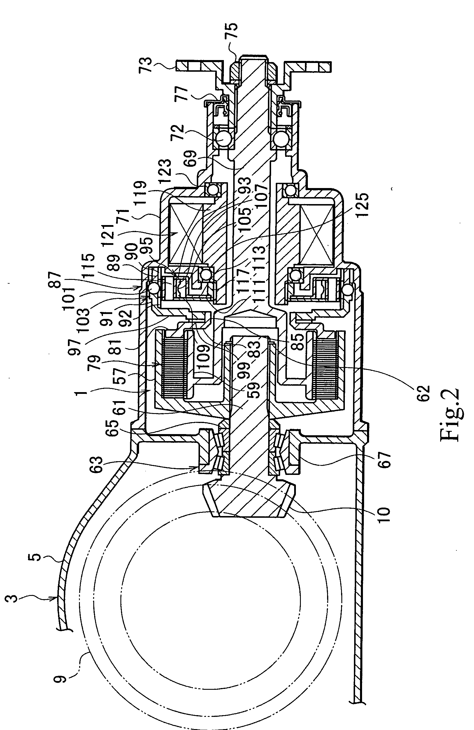
[0201] In the present embodiment, a torque transmission coupling IN is provided in a transfer device 3A. In the torque transmission coupling IN, the output shaft 61 or the output shaft 267, which is shown in FIGS. 2 to 9, is coupled to output the torque transmitted from a transmission 21 in FIG. 10. The shaft 61 or 267 is coupled to the propeller shaft 35 through the constant-velocity universal joint 33.
[0202] A gear 141 is integrally provided in the output shaft 61 or 267. A chain 147 is wound between the gear 141 and a gear 145 provided on a transmission shaft 143. The transmission shaft 143 is connected to a transmission shaft 151 through a propeller shaft 149. A pinion gear 153 of the transmission shaft 151 engages a ring gear 23...
PUM
 Abstract
Description
Claims
Application Information