Compound ultrasound imaging method

a technology of ultrasound imaging and compounding, applied in the field of compound ultrasound imaging method, can solve the problems of loss of useful data for image compounding, method cannot be applied, persistence effect will be noticed

Inactive Publication Date: 2004-09-30
ULTRASONIX MEDICAL CORP
View PDF2 Cites 15 Cited by
  • Summary
  • Abstract
  • Description
  • Claims
  • Application Information

AI Technical Summary

Benefits of technology

[0020] In another embodiment, the present invention acquires frames at a faster frame rate overall, but by cutting the unused parts, reduces the persistence effect happening after compounding the component frames.

Problems solved by technology

In some cases such as small footprint phased-array probes, phased linear arrays as well as some linear arrays and convex arrays this method cannot be applied because the side lobes are too visible and generate too many artifacts.
Furthermore, when frames with different angles are generated, non-overlapping areas are typically not shown because they typically belong to angled images which exhibit more side lobe artifacts when not averaged.
This leads to loss of useful data for image compounding.
Since the compound imaging method is based on compounding N component frames, there is an inherent drawback; that is a persistence effect will be noticed, especially when N gets larger.
This reduces the focusing quality and increases side lobes and artifacts especially when focusing with angles.

Method used


Image

  • Compound ultrasound imaging method
  • Compound ultrasound imaging method
  • Compound ultrasound imaging method

Examples


Embodiment Construction

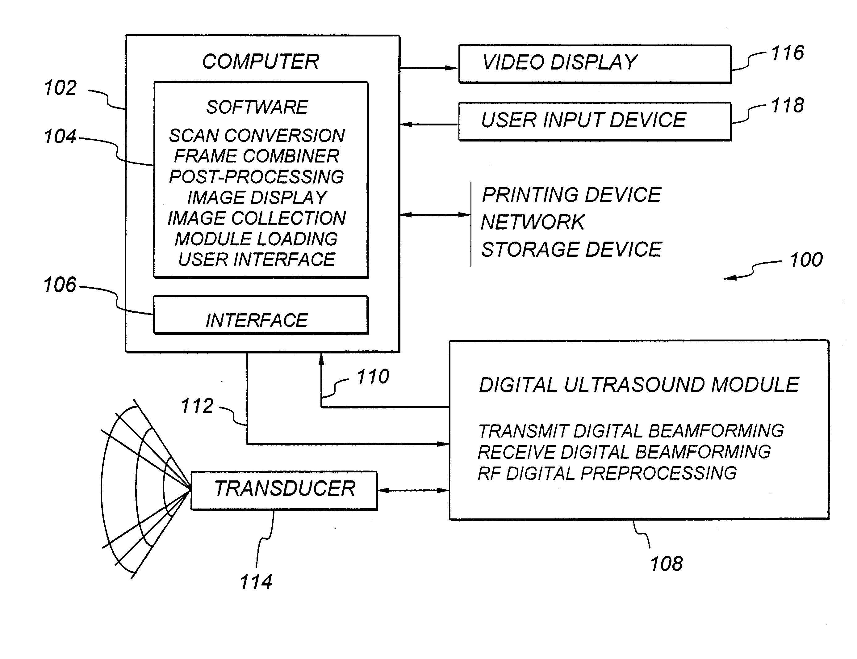
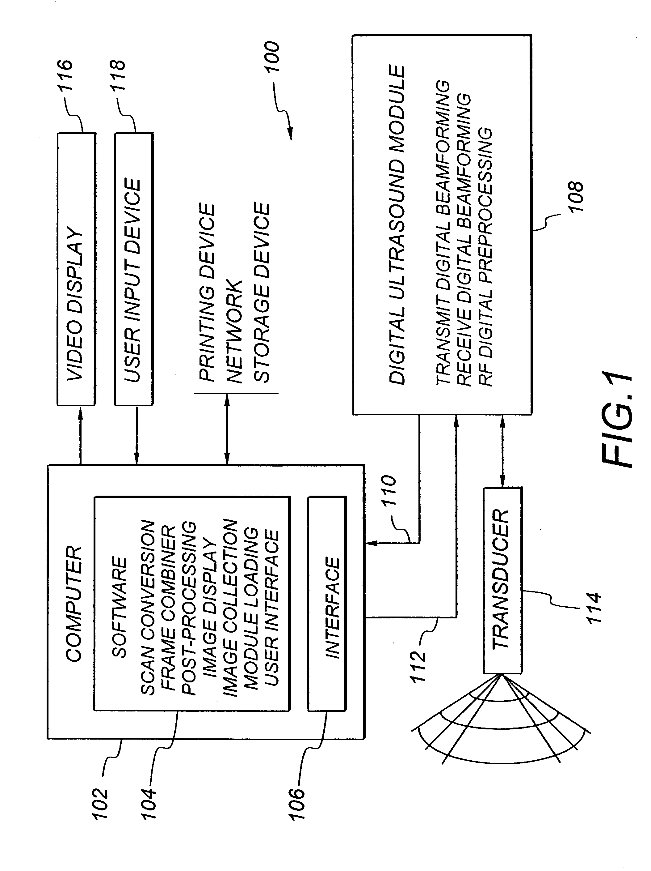
[0031] FIG. 1 shows an ultrasound imaging system 100 for producing ultrasound images. The ultrasound system 100 includes a digital ultrasound module 108 and a computer 102. The ultrasound module 108 is coupled to a transducer 114. The transducer 114 generates and receives acoustic signals. The acoustic signals that are generated by the transducer 114 are directed towards a body region of a patient, and then reflected back to the transducer 114 as echo signals. The echo signals obtained by the transducer 114 are sent back to the ultrasound module 108. The ultrasound module 108 processes the echo signals to extract data vectors called preprocessed digital data 110. The preprocessed digital data 110 is sent to the computer 102. The computer 102 then stores the preprocessed digital data 110 and performs a display processing in real-time to produce an ultrasound diagnostic image. The ultrasound diagnostic image is displayed on a video display 116 connected to the computer 102. See U.S. P...


PUM


Abstract

A compound ultrasound imaging method includes the steps of acquiring component frames with different scanline properties, such as different angles, scanline durations, control voltages, etc., and compounding them in real-time.

Description

[0001] The present invention relates to compound ultrasound diagnostic imaging. In particular, the present invention relates to an ultrasound diagnostic imaging method of acquiring and merging a succession of ultrasound images with different properties to yield an ultrasound image in real time.BACKGROUND--DESCRIPTION OF PRIOR ART[0002] Ultrasound imaging systems are used in medicine to explore internal areas of a patient's body. Ultrasonic imaging is non-destructive and versatile and can provide high quality diagnostic images.[0003] A typical medical ultrasound imaging system has a transducer, a custom built electronic controller, and a user interface. The transducer typically has several piezoelectric transducer elements regularly placed on a frame. The transducer may have elements arranged in any of several different geometries, depending upon the medical application for which the transducer will be used. The controller drives the transducer and collects and processes data from th...

Claims


Application Information

Patent Timeline
Patent Type & Authority Applications(United States)
IPC IPC(8): G01S15/89
CPCG01S15/8995G01S7/52085
Inventor PELISSIER, LAURENTFATTAH, ERICDICKIE, KRIS
Owner ULTRASONIX MEDICAL CORP
Why Eureka
Try Eureka