Clutch arrangement

a technology of clumping and lining, which is applied in the direction of rotary couplings, couplings, mechanical devices, etc., can solve the problems of friction elements subjected to extreme thermal stress, friction lining separation, adhesive bonding stress,

Inactive Publication Date: 2004-10-07
ZF SACHS AG
View PDF13 Cites 24 Cited by
  • Summary
  • Abstract
  • Description
  • Claims
  • Application Information

AI Technical Summary

Problems solved by technology

The result of this is that, in spite of the ability of the various fluid transport surfaces to build up a circulation of fluid flowing around the friction elements, the friction elements are subjected to extreme thermal stress in the area of their friction lining carriers, which are usually made of metal sheet or plate m

Method used


Image

  • Clutch arrangement
  • Clutch arrangement
  • Clutch arrangement

Examples


Embodiment Construction

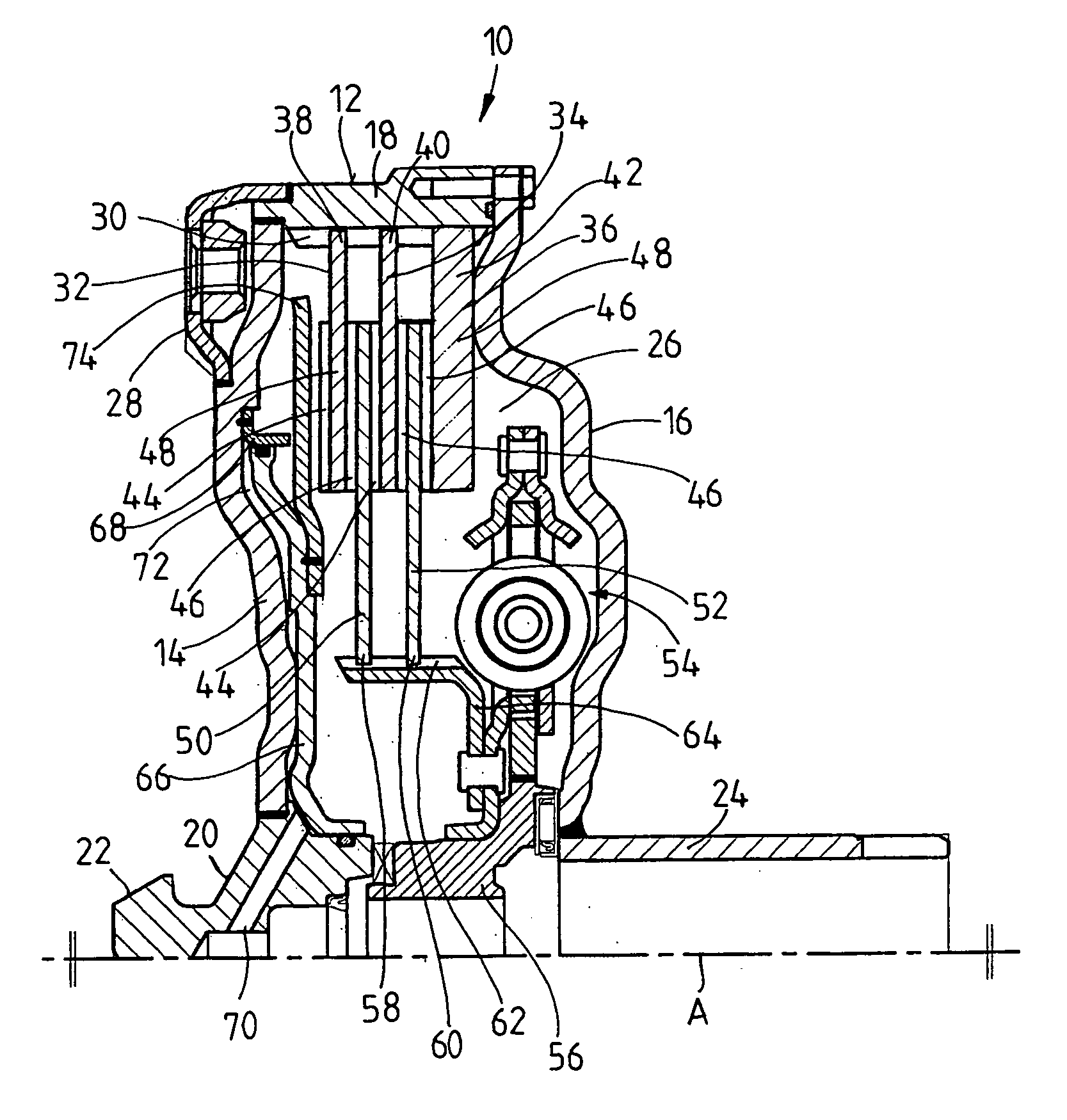
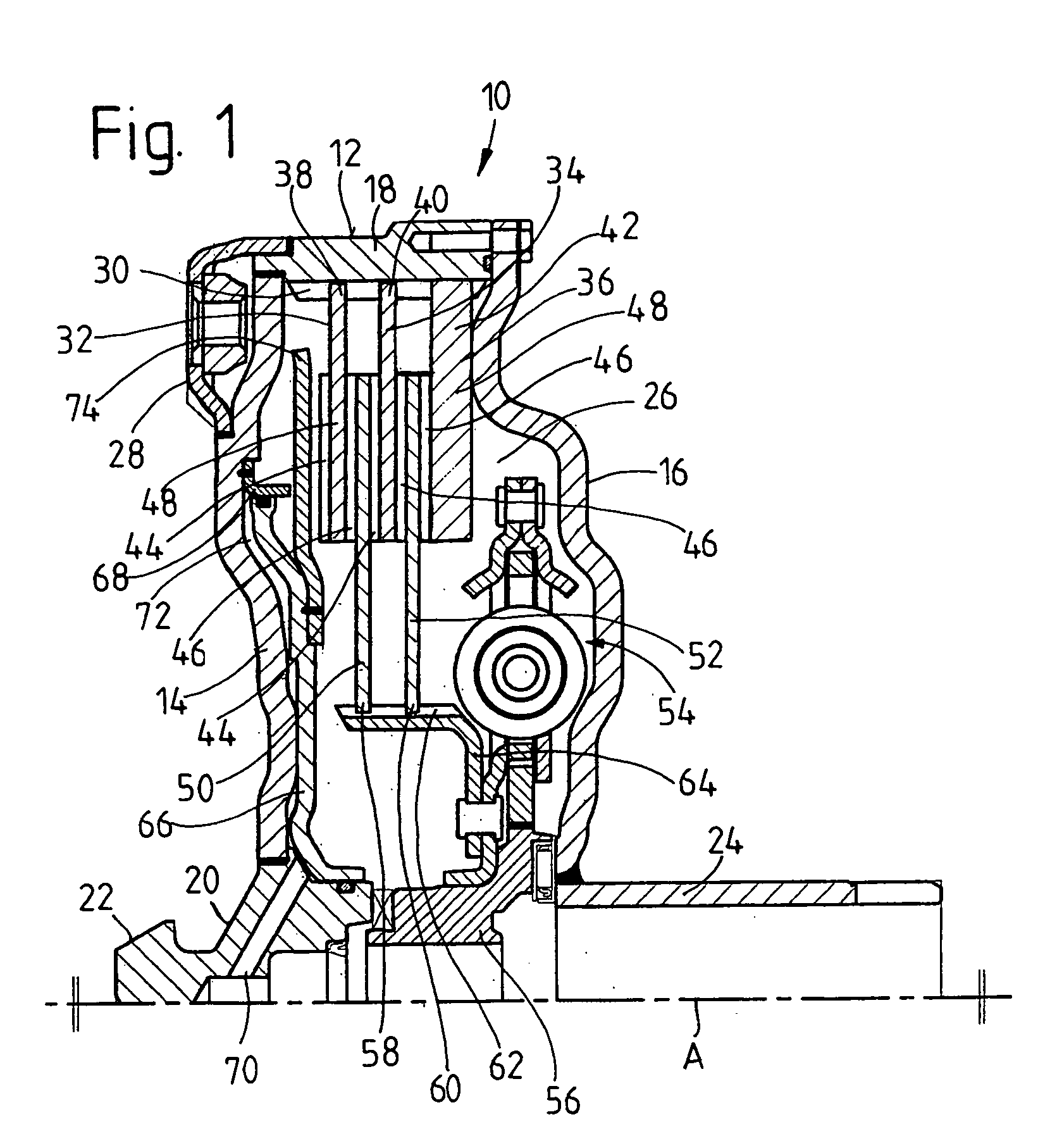
[0019] FIG. 1 shows a wet-running clutch arrangement 10 according to the invention. The clutch arrangement 10 comprises a housing 12, which has two essentially disk-like housing parts 14, 16, connected to each other in their outer radial areas by means of a ring-like housing part 18. The housing part 14 is also connected in its radially inner area to a housing hub 20, which carries a bearing journal 22. The journal engages with, for example, an appropriate centering receptacle in a drive shaft. The housing part 16 is rigidly connected radially on the inside to a so-called pump hub 24, by means of which a pump, mounted, for example, on a gearbox, can be operated to build up a fluid pressure, so that fluid can be supplied to the interior 26 of the housing 12. The housing 12 can be connected nonrotatably to a drive shaft, such as the crankshaft of an internal combustion engine, at several connecting points 28 by means of a flexplate or the like.

[0020] The radially outer, ring-like hous...


PUM


Abstract

A clutch arrangement, especially for a motor vehicle, comprises a housing arrangement which can be filled with fluid; at least one first friction element connected to the housing arrangement for rotation in common around an axis of rotation; and at least one second friction element connected to a power takeoff element for rotation in common around the axis of rotation (A), which second element can be brought into contact with at least one first friction element to produce a frictional interaction. The at least one first friction element or the at least one second friction element has a friction lining carrier which carries a friction lining arrangement on each frictionally active axial side of the friction element. At least in the case of one friction element with a friction lining carrier carrying a friction lining arrangement an arrangement of fluid transport surfaces is provided to produce a circulation of fluid which flows around at least certain areas of the friction elements.

Description

[0001] 1. Field of the Invention[0002] The present invention pertains to a clutch arrangement, especially for a motor vehicle, comprising a fluid-filled or fluid-fillable housing arrangement; at least one first friction element, which can rotate in common with the housing arrangement around an axis of rotation; and at least one second friction element, which can rotate in common with a power takeoff element around an axis of rotation, which second friction element can be brought into contact with at least one first friction element to produce a frictional interaction.[0003] 2. Description of the Related Art[0004] A clutch arrangement of this type is known from DE 101 25 628 A1. In an embodiment shown in this publication, the first and second friction elements, i.e., the friction lining carriers of these elements, carry a friction lining on one axial side, whereas, on the other axial side, the friction lining carrier enters directly into frictional interaction with a friction lining ...

Claims


Application Information

Patent Timeline
IPC IPC(8): F16D13/52F16D13/64F16D13/62F16D13/72F16D25/12
CPCF16D13/52F16D13/648F16D13/72F16D25/0638
Inventor SUDAU, JORG
Owner ZF SACHS AG
Why Eureka
Try Eureka