
Automatic channel selection in a radio access network

Inactive Publication Date: 2004-10-14
INTERDIGITAL CE PATENT HLDG
View PDF13 Cites 18 Cited by
  • Summary
  • Abstract
  • Description
  • Claims
  • Application Information

AI Technical Summary

Benefits of technology

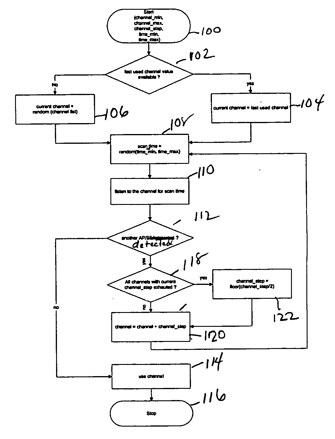
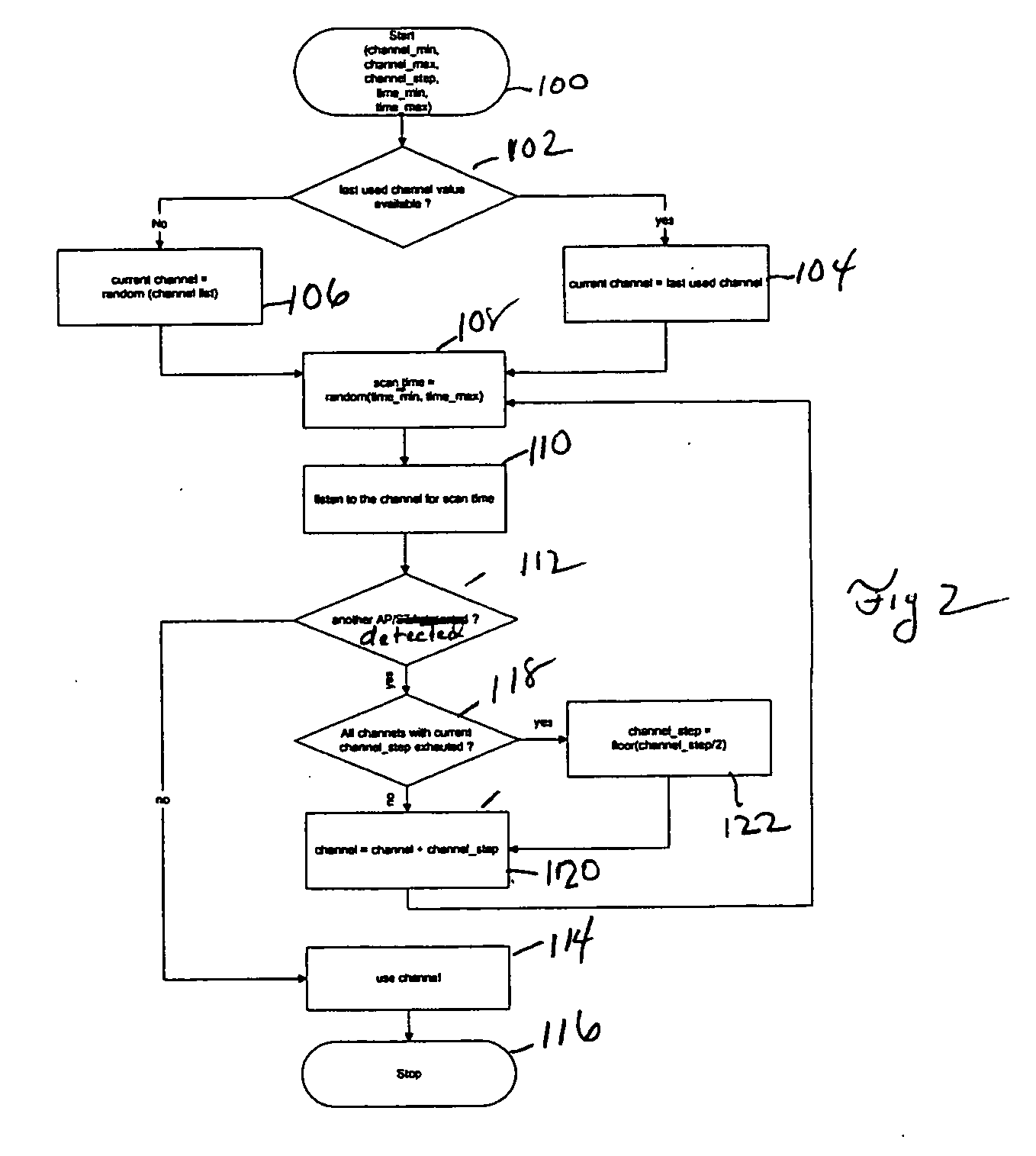
[0012] Following step 100, the AP makes a check during step 102 to determine whether the last channel used by the AP still remains available. If so, then AP selects the last channel used as the current channel during step 104. Checking the availability of the previously used channel increases efficiency. Often times, the AP can re-use the last channel before another AP claims the channel. Should the AP find the last channel unavailable, then the AP will select a channel at random from the available channel list during step 106.

Problems solved by technology

Unfortunately, this approach doesn't work well when geographically adjacent APs belong to wireless LANs operated by separate entities that lack the incentive to cooperate to reduce radio frequency interference.
Thus, radio interference will occur when geographically adjacent APs transmit on adjacent channels.
These approaches incur the disadvantage of requiring either full-time administrative control over geographically adjacent APs or requiring them to implement specific protocol modifications.

Method used


Image

  • Automatic channel selection in a radio access network
  • Automatic channel selection in a radio access network
  • Automatic channel selection in a radio access network

Examples


example 2

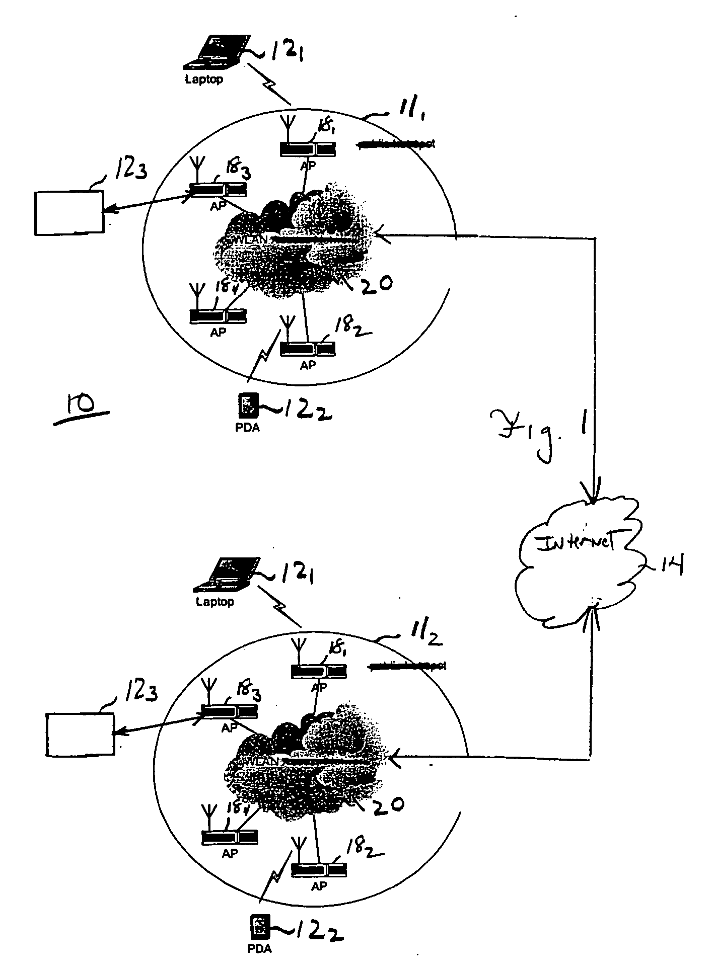
[0023] Assume that the APs 18.sub.1, 18.sub.2, and 18.sub.3 within the radio access network 11.sub.1 use channels #1, #6, and #11, respectively. Further assume that AP 18.sub.4 in the same radio access network now commences operation and implements the channel selection method according to present principles. In implementing the channel selection method, assume that the AP 18.sub.4 selects the following parameter values: channel_min=1, channel_max=11, channel_step=5, time_min=500, time_min=1000. Additionally assume that AP 18.sub.4 did not store information about the previously used channel.

[0024] Using the channel selection method of the present principles, the AP 18.sub.4 will first select a channel in accordance with the relationship

current_channel=random(1, 6, 11)

[0025] Assume that AP 18.sub.4 selects channel #6 as in the previous example. Next, the AP 18.sub.4 selects the value for the parameter scan_time in accordance with the relationship:

scan_time=random(500,1000)

[0026] Assu...

example 3

[0032] This example describes scenario when two APs, such as APs 18.sub.2 and 18.sub.3 within the radio access network 11.sub.1, both startup simultaneously, while another AP, such as AP 18.sub.1 in the same network, currently uses channel #1. Assume that both APs 18.sub.2 and AP 18.sub.3 utilize the following parameter values: channel_min=1, channel_max=11, channel_step=5, time_min=500, time_min=1000. Also, assume that neither AP 18.sub.2 nor AP 18.sub.3 store information about the channel each previously used.

[0033] Using the method of the present principles, both of the APs 18.sub.2 and 18.sub.3 will each select a current channel as follows in accordance with the relationships:

[0034] For AP 18.sub.2

current_channel=random(1, 6, 11)

[0035] Assume AP 18.sub.2 has randomly selected channel #6.

[0036] For AP 18.sub.3

current_channel=random(1,6,11)

[0037] Also assume AP 18.sub.3 selects channel #6. If both AP 18.sub.2 and AP 18.sub.3 were to actually claim the same channel, severe interfer...


PUM


Abstract

Within a radio access network (111, 112) an access point (181, 182, 183 and 184) selects a channel by first randomly choosing a channel from those available for use. The Access Point then monitors the channel for a random interval to determine if the channel is presently carrying traffic. The Access Point will select the channel unless the channel is in use by another AP. If so, then the AP will select another channel and commence monitoring for a random interval in order to determine whether the channel is available. The AP will continue to choose channels until a suitable channel is found, or all available channels have been exhausted.

Description

[0001] This invention relates to a technique for automatically selecting channels in a Radio Access Network, such as a wireless Local Area Network (LAN).[0002] Advances in the field of wireless LAN technology has led to the availability of relatively inexpensive wireless LAN equipment, which, in turn, has resulted in the emergence of publicly accessible wireless LANs (e.g., "hot spots") at rest stops, cafes, libraries and similar public facilities. Presently, wireless LANs offer users access to a private data network, such as a Corporate Intranet, or a public data network such as the Internet. The relatively low cost to implement and operate a wireless LAN, as well as the available high bandwidth (usually in excess of 10 Megabits / second) makes the wireless LAN an ideal access mechanism through which a mobile terminal user can exchange packets with an external source.[0003] Within the wireless LAN, there exists one or more Access Points (APs) each typically comprising a transceiver f...

Claims


Application Information

Patent Timeline
IPC IPC(8): H04L12/28H04W72/04H04W88/08
CPCH04W24/00H04W72/02H04W88/08H04W72/04
Inventor MATHUR, SAURABH
Owner INTERDIGITAL CE PATENT HLDG
Learn More